

An aluminum electrolytic capacitor must be installed and energized with the polarity specified by its manufacturer; reverse voltage is not an acceptable operating condition. Nippon Chemi-Con reports that about 1 V reverse bias can reduce capacitance, while 2–3 V can also increase dissipation factor and leakage current. This guide turns that safety principle into six OEM checks for drawings, PCB layout, assembly, inspection and containment.
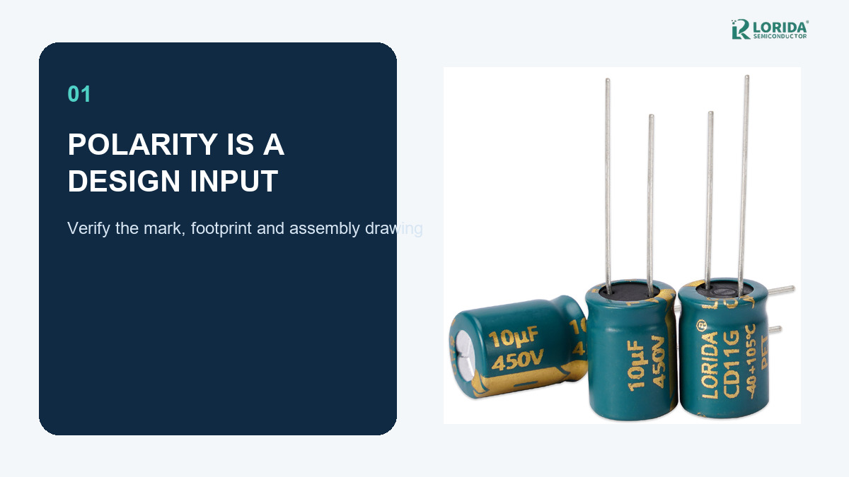
Treat polarity as a controlled drawing and PCB attribute, not an operator memory item.
Verify the body mark, terminal geometry and board legend against the exact approved part.
Check negative transients at the capacitor terminals under startup, shutdown and fault conditions.
Quarantine any unit exposed to reverse polarity; a normal-looking can is not proof of health.
Why does aluminum electrolytic capacitor polarity matter?
The anode and cathode are not interchangeable
Polar aluminum electrolytic capacitors use an anode foil with a formed dielectric layer and a cathode foil that does not provide the same reverse withstand function. Nippon Chemi-Con therefore instructs designers never to apply reverse or AC voltage to a polar device. Its published 105°C reverse-voltage example uses a 25 V, 47 µF radial capacitor and shows that the electrical condition changes as reverse bias increases. These numbers are an example from that manufacturer, not a universal allowance or a LORIDA rating.
Small reverse voltage is still a design failure
Nippon Chemi-Con states that roughly 1 V reverse voltage can reduce capacitance. At 2–3 V, it reports capacitance loss, increased dissipation factor and increased leakage current, with higher reverse voltage capable of operating the pressure-relief vent or causing damage. Nichicon likewise explains that a large current can begin flowing at low reverse voltage. The correct engineering target is therefore zero unintended reverse bias, not a guessed “safe” negative margin.
What six checks should an OEM complete before approval?
Checks 1–2: exact part marking and footprint orientation
Read the exact product drawing. Identify which sleeve stripe, case mark, terminal symbol or lead geometry denotes the cathode for the selected series. Do not transfer assumptions from another case style.
Match the PCB footprint. Compare the approved drawing with pad polarity, silkscreen, assembly view and BOM designator. For radial parts, a shorter lead may indicate the cathode, but trimmed or formed leads can remove that cue; the body mark and drawing remain authoritative.
Checks 3–4: circuit waveform and assembly controls
Measure voltage at the component terminals. Capture startup, normal load, shutdown, hot restart and credible fault recovery. A positive average bus voltage can still include a negative transient.
Build polarity into the process. Use feeder orientation, keyed trays where applicable, AOI criteria and a first-article photograph. Inspection criteria should show the accepted body-mark direction, not merely state “check polarity.”
Checks 5–6: discharge path and containment
Control residual voltage. Panasonic notes that re-striking voltage can occur and recommends discharging through a resistor of about 1 kΩ in the cited precaution; designers must confirm the value for their own circuit and energy limits.
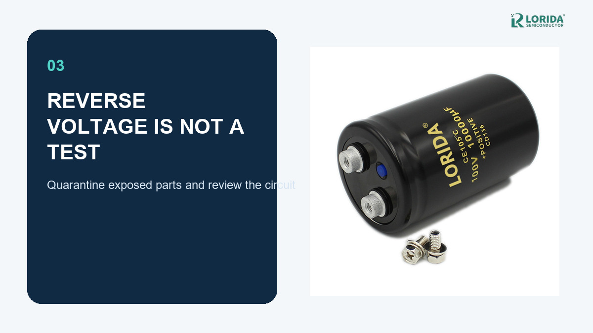
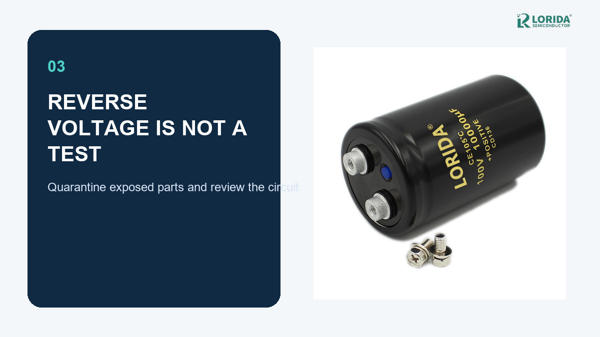
Define the reaction to exposure. If reverse connection or an unknown waveform occurred, stop power, discharge safely, quarantine the capacitor and review the circuit. Do not return the component to production based only on appearance or a quick capacitance reading.
How should buyers document polarity in an RFQ?
Send operating evidence, not only capacitance and voltage
A useful RFQ includes the required capacitance and rated voltage, the actual terminal waveform, maximum ambient and case temperature, ripple-current spectrum, case style, terminal or lead arrangement, PCB footprint, mounting direction and expected inspection method. If the circuit can reverse polarity, state that explicitly; a polar capacitor should not be treated as a substitute for a bipolar component.
Use a polarity-control table
| Control point | Evidence to provide | Release criterion |
|---|---|---|
| Part | Series drawing and label photo | Mark and terminals agree |
| PCB | Footprint, legend and assembly view | No polarity conflict |
| Circuit | Terminal waveform in all modes | No unintended reverse bias |
| Assembly | First article and AOI rule | Approved orientation detected |
What should validation and failure analysis include?
Validate at the capacitor terminals
Probe placement matters. Measure directly across the capacitor terminals with the intended polarity sign convention and sufficient bandwidth to capture switching or relay events. Repeat the check with minimum and maximum input, load steps, commanded shutdown, emergency stop and rapid restart. Record the waveform with the exact hardware and firmware revision so a later change cannot silently invalidate approval.
Do not energize a suspect capacitor again
Reverse voltage can drive leakage current, heating and gas generation before visible evidence appears. The component may later vent, leak, short or lose capacitance. A suspect unit should be treated as nonconforming material and evaluated through the organization’s safety and failure-analysis process. Replacement alone is incomplete if the board legend, wiring harness, assembly instruction or transient-producing circuit remains unchanged.
How can sourcing and quality teams prevent polarity escapes?
Use one controlled polarity record across departments
Create a single release record that combines the supplier drawing, approved label photograph, PCB pad map, board legend, feeder direction, AOI example and first-article result. Give every item the same part number and revision. When engineering changes a terminal option, case style, footprint or approved source, require quality and manufacturing to review the polarity record again. This prevents a correct schematic from being paired with an outdated assembly image or a visually similar substitute.
Audit the negative path as well as the positive connection
During incoming and line audits, trace both capacitor terminals through the real harness and PCB instead of checking only the marked positive node. Confirm meter lead convention before recording a waveform. Keep a photograph of the probe points and the oscilloscope polarity convention with the approval report. This simple evidence makes later troubleshooting faster and reduces the risk that an inverted measurement is mistaken for a real reverse-voltage event.
Frequently asked questions
Can an aluminum electrolytic capacitor tolerate a small reverse voltage?
No reverse voltage should be designed into a polar aluminum electrolytic capacitor. Nippon Chemi-Con reports that even about 1 V can reduce capacitance, while 2–3 V can also increase dissipation factor and leakage current. Those observations are failure evidence, not allowable ratings. Measure the complete terminal waveform during startup, shutdown and faults. If reverse bias is possible, redesign the circuit or select a component technology specifically intended for that waveform.
Does the stripe on an electrolytic capacitor always mark negative?
The body marking must be interpreted using the exact series drawing. Many leaded aluminum electrolytic capacitors use a sleeve stripe to identify the cathode, but case styles and marking conventions differ. SMD parts also use package marks that must be read with their mounting drawing. Procurement and assembly teams should approve one annotated image that connects the body mark, terminal numbers, PCB pads and board legend for the exact ordered part.
Can a bipolar electrolytic capacitor be used directly on AC mains?
No; “bipolar” does not automatically make an electrolytic capacitor suitable for an AC mains application. Nippon Chemi-Con explicitly notes that even bipolar electrolytic capacitors must not be used as general AC capacitors. The correct choice depends on the waveform, voltage, frequency, safety class and applicable standard. Use a component whose manufacturer specification explicitly covers the intended AC duty rather than inferring suitability from the word bipolar.
What information should I send for a polarity review?
Send the schematic, capacitor-terminal waveform, PCB footprint, assembly drawing and the candidate part specification. Include startup, steady-state, shutdown, hot-restart and fault-recovery conditions; maximum temperature; ripple spectrum; case style; terminal arrangement and inspection method. LORIDA can then compare candidate dimensions and marking conventions with your RFQ, while final circuit approval remains with the equipment designer and the applicable safety process.
Review your capacitor polarity controls
Send the schematic, terminal waveform, footprint, mounting drawing and candidate specification for a technical quotation review.
Sources
Last Updated: 2026-10-05


