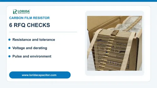
Select a carbon film resistor by resistance, tolerance, continuous voltage, thermal derating, pulse duty and mechanical/environmental requirements—not by wattage or color bands alone. A useful RFQ includes the real circuit voltage and current, local temperature, surge waveform, body and lead dimensions, coating or flame requirement and the exact evidence required for sample approval.
Resistance, power and maximum working voltage must be checked together.
A higher wattage label does not automatically improve pulse or voltage performance.
Body size, coating, leads and packaging are part of the approved specification.
External datasheet examples must never be reused as unverified LORIDA ratings.
1. Define resistance and tolerance at circuit level
Start from the acceptable output error
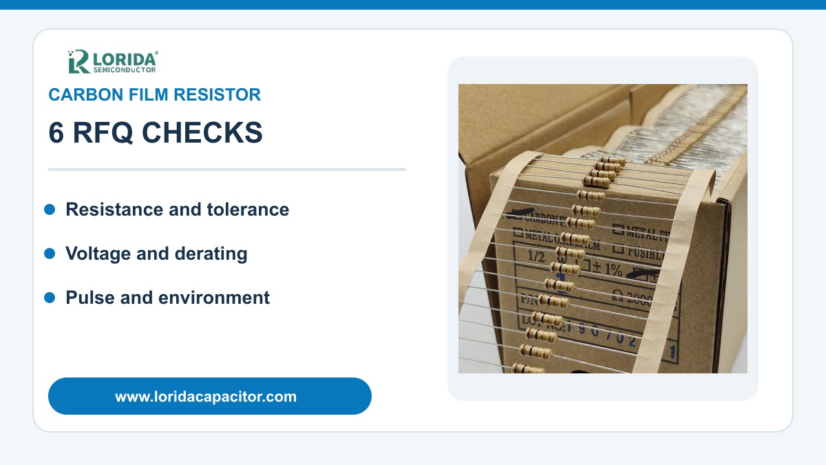
State nominal resistance, permitted initial tolerance and the maximum circuit error across operating temperature. Include the source tolerance, sensing accuracy and the effect of adjacent components. Color bands are useful for identification, but they do not prove voltage, pulse, coating, stability or qualification. For replacement work, attach the original full part number and datasheet revision rather than relying on body color.
Vishay’s carbon-film selector guide provides an external comparison: LCA0207 and LCA0414 list ±2% and ±5% tolerance options, while the broader carbon-film portfolio highlights tolerance down to ±1%. These values belong only to the cited Vishay families. They show why a buyer should specify the actual error budget and require a matching order-code table from the proposed supplier.
2. Verify resistance range and exact construction
Technology names do not guarantee identical ranges
Carbon-film families can be optimized for general purpose, pulse duty, high voltage or high-frequency service. State the required value and ask whether it is available in the requested size, tolerance, coating and packaging. Do not assume the highest and lowest values in a portfolio overview apply to every model.
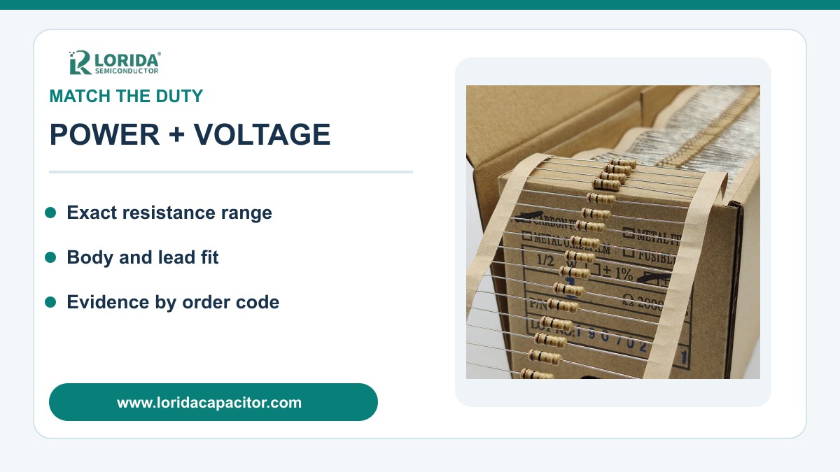
The Vishay selector guide lists a portfolio-wide resistance span of 0.22 Ω to 500 MΩ. Within that guide, LCA0207 is shown with ranges of 1 Ω to 1 MΩ and 0.22 Ω to 5.1 MΩ depending on tolerance, while LCA0414 extends the wider option to 10 MΩ. These are external-series examples, not LORIDA specifications. A compliant quotation should identify one exact model, resistance code, tolerance code and packaging code.
3. Calculate continuous power and thermal derating
Use local temperature, not room temperature
Calculate worst-case dissipation using P=I²R or P=V²/R, including supply and resistance tolerances. Then compare the result with the series derating curve at the resistor’s local ambient temperature. Board heating, enclosure temperature, airflow, lead length and spacing can make the component hotter than a bench measurement suggests.
As an external example, Vishay’s selector guide lists 0.35 W for LCA0207 and 0.6 W for LCA0414. The portfolio overview spans 0.25 W to 120 W and -55 °C to +175 °C, but those portfolio limits must not be applied to an arbitrary part. Request the exact reference temperature, derating curve and permissible film temperature, then measure the installed component under the worst expected load and cooling condition.
4. Check working voltage separately from wattage
High resistance can become voltage-limited first
A resistor can remain below its calculated wattage while exceeding maximum working voltage. State maximum continuous voltage, polarity, expected overshoot, insulation requirement, creepage and clearance. Check P=V²/R and the series voltage limit independently. If a string of resistors shares voltage, consider tolerance, contamination and transient distribution instead of assuming equal division.
Vishay’s B/T high-voltage carbon-film datasheet illustrates the separation: it lists ratings from 0.5 W to 10 W, maximum working voltages from 2.5 kV to 40 kV, and resistance ranges reaching 500 MΩ for listed models. Those figures apply only to that specialized family, not to ordinary axial carbon-film parts. Use them only as evidence that voltage, power and resistance must be quoted and verified as separate limits.
5. Describe every pulse and abnormal event
Average power cannot define surge capability
Provide pulse peak voltage or current, pulse width, waveform, repetition period, source impedance and total event count. Startup, capacitor discharge, relay switching and fault clearing can concentrate energy differently even when their average power is equal. Ask for the correct single-pulse or repetitive-pulse curve for the exact resistance value and ambient temperature.
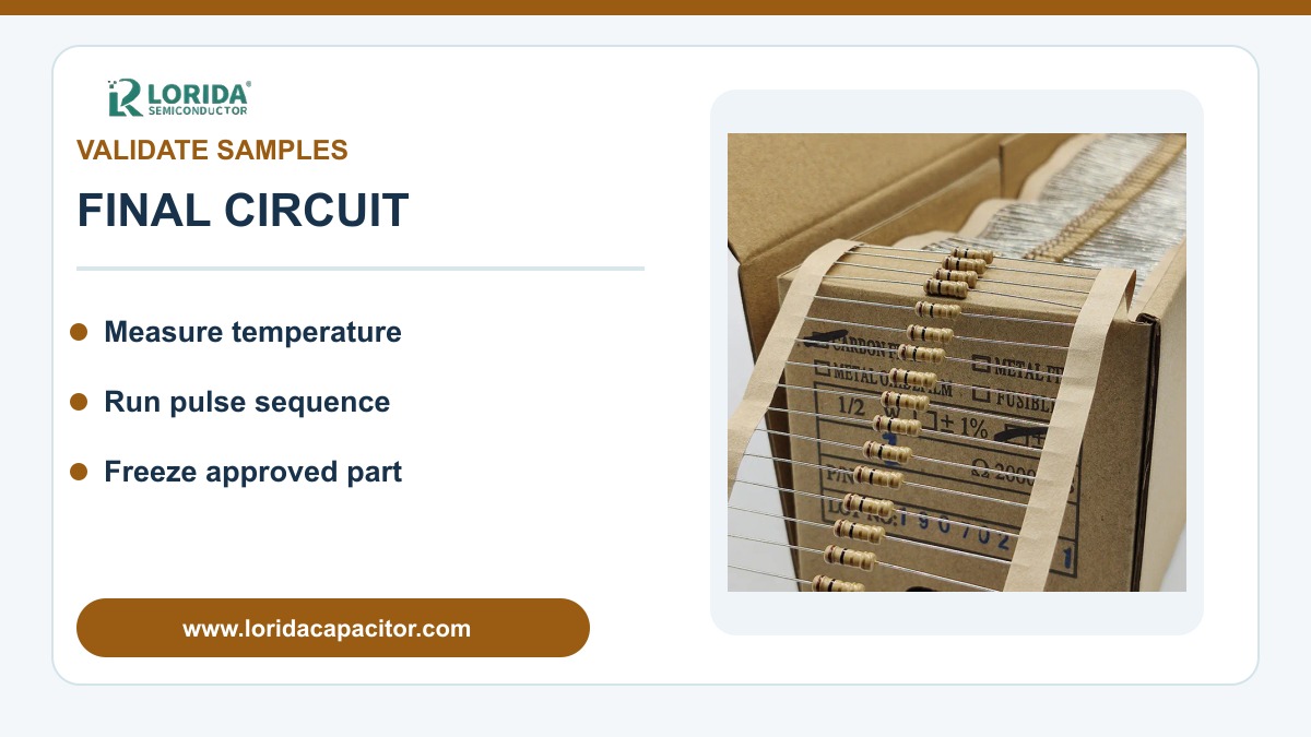
Do not infer pulse capability from body size or the words “carbon film.” Film geometry, trimming, coating and voltage distribution affect localized stress. Coordinate abnormal-duty behavior with the fuse or protection device and state whether flameproof or fusible construction is required. During sample validation, capture the real waveform, record resistance before and after the sequence and inspect the coating and leads.
6. Freeze mechanical, environmental and evidence fields
Approve a traceable order code, not a visual substitute
| RFQ field | Provide | Decision controlled |
|---|---|---|
| Electrical | Resistance, tolerance, voltage and current | Error, power and voltage margin |
| Thermal | Ambient, board temperature and airflow | Derating and film temperature |
| Pulse | Peak, width, waveform, period and count | Overload and surge survival |
| Mechanical | Body, leads, forming, spacing and height | PCB fit and assembly |
| Environment | Humidity, cleaning, corrosion and vibration | Coating and qualification |
| Evidence | Order code, datasheet revision and test plan | Purchasing control |
Confirm body length and diameter, lead diameter, lead forming, PCB spacing, mounting orientation, cleaning process, humidity, corrosive exposure, vibration and packaging. Vishay’s LCA product information cites moisture resistance and 1000-hour long-term stability, each with maximum resistance change of ±1.5% R for that series. These exact figures are useful comparison evidence only; the proposed part needs its own conditions and acceptance limits.
Compare the LORIDA carbon film resistor category with the metal film resistor category and wirewound resistor category. Send the circuit duty, original part number and drawing through the LORIDA contact page.
Frequently Asked Questions
Can I replace a carbon film resistor by matching color bands?
No, matching color bands does not prove equal electrical or mechanical duty. Bands normally identify resistance and tolerance, but they do not fully define maximum working voltage, pulse curve, thermal derating, coating, stability, flame behavior, body size or lead geometry. Send the original full part number and circuit conditions. Compare the proposed series table and order code, then validate samples at maximum voltage, load and temperature. Record resistance before and after the required pulse or endurance sequence so purchasing cannot later substitute a visually similar part without engineering review.
Is a higher-wattage carbon film resistor always safer?
No, a higher nominal wattage does not automatically provide the required voltage, pulse or environmental performance. A larger body may dissipate more continuous heat, yet the exact series can still have a working-voltage limit or a pulse curve that excludes your waveform. Calculate continuous power and voltage separately, use the derating curve at local temperature and compare the real surge with the correct pulse graph. Also confirm body dimensions and lead spacing because a higher-wattage replacement can create assembly, clearance or vibration problems.
When should I compare carbon film with metal film?
Compare technologies when accuracy, temperature drift, noise, pulse duty, cost or availability materially affects the circuit. Do not decide from the technology label alone. Build the same RFQ for both candidates: resistance, tolerance, temperature range, voltage, continuous power, pulse waveform, dimensions, environment and qualification. Request exact order-code evidence. Metal-film options are often considered for tighter accuracy and stability, while particular carbon-film constructions may address general-purpose, pulse or high-voltage needs. Validate the final candidates under identical circuit and thermal conditions.
What should a carbon film resistor RFQ contain?
Provide the electrical duty, thermal environment, surge waveform, mechanical drawing and approval evidence. Include nominal resistance, tolerance, maximum continuous voltage and current, calculated power, local ambient and board temperature, pulse peak and width, repetition, body and lead dimensions, forming, coating or flame requirement, humidity, cleaning, vibration and packaging. Attach the original order code for replacement projects. Ask for the proposed full part number, current datasheet, derating and pulse curves, samples and a written validation plan tied to your acceptance limits.
Sources: Vishay LCA standard carbon film leaded resistor product information; Vishay Carbon Film Resistors selector guide VMN-SG2034-1205; Vishay B/T high-voltage carbon film datasheet, Document 31039.
Prepare a carbon film resistor RFQ
Send the voltage, power, pulse waveform, environment and mechanical drawing for a datasheet-based sample review.
Send your carbon film resistor requirementsLast Updated: September 14, 2026