Technical Guide · Leakage-Current Verification
Measure aluminum electrolytic capacitor leakage current only after applying the specified DC voltage, polarity, temperature and stabilization time from the applicable datasheet. A high reading taken during initial charging, at the wrong temperature or without isolating fixture leakage is not a valid pass/fail result.
Key Takeaways
Separate charging current from steady leakage current by observing the specified waiting time.
Use the exact series limit; a common formula such as 0.01CV or 3 µA is not universal.
Control polarity, voltage, ambient temperature, fixture insulation and discharge before every test.
Record the full current-versus-time trace when evaluating stored parts or an unfamiliar lot.
What Does Leakage Current Mean?
It is not the initial charging current
When DC voltage is first applied, the capacitor draws charging current. That current falls as the electric field builds and the dielectric reaches a stable condition. Leakage current is the much smaller current that remains through the dielectric and electrolyte after the specified stabilization interval. Nippon Chemi-Con explains that the value decreases with time toward a steady state, which is why its published limits are defined several minutes after voltage application rather than at switch-on.
This distinction matters in incoming inspection. A meter sampled immediately after connection may show a large but normal transient. Rejecting parts from that first number creates false failures; ignoring a current that remains high after the defined interval can hide damaged dielectric, contamination, reversed polarity or storage-related deterioration.
The limit belongs to a specific series
For one Nichicon UT series example, leakage current after two minutes at rated voltage is limited to the greater of 0.01CV or 3 µA, where C is capacitance in microfarads and V is rated voltage in volts. Other series use different coefficients, minimum values or test times. Nichicon's leaded catalog also shows that some high-voltage ranges use formulas such as 0.1CV + 40 µA or 0.04CV + 100 µA after one minute. Those are series rules, not interchangeable industry constants.
How Should the Test Be Set Up?
Use a protected DC measurement circuit
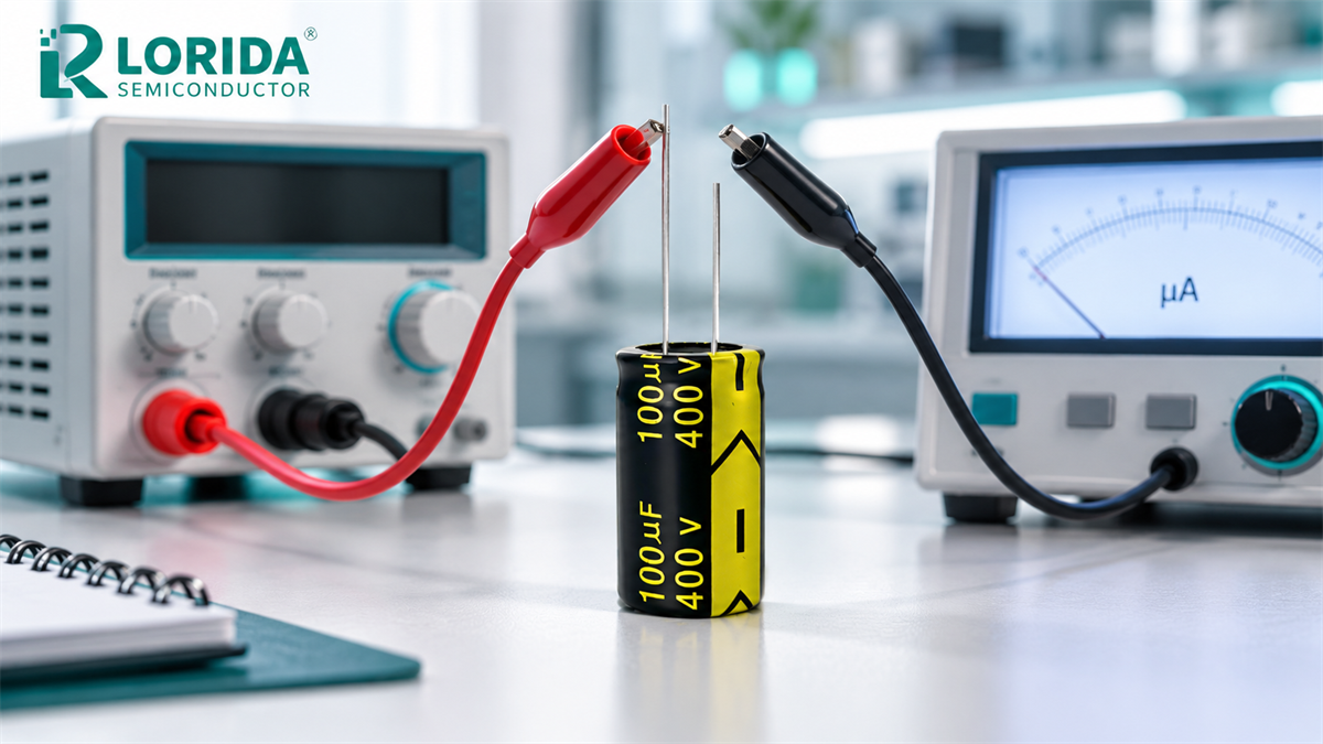
A practical setup uses a regulated DC source, current-limiting protection, a microammeter or picoammeter with suitable range, and a fixture whose insulation resistance is high enough that fixture current is negligible relative to the part limit. Confirm the supply polarity before connecting the capacitor. Aluminum electrolytic capacitors are polarized; reverse voltage can rapidly increase current, heat and internal gas generation.
Choose protection so an abnormal part cannot discharge unsafe energy through the meter. The protection value and charging method should come from the approved test specification. For stored components that require dielectric reforming, Nippon Chemi-Con describes one voltage-treatment example using an approximately 1 kΩ series resistor and rated voltage for 30 to 60 minutes. That procedure is a conditioning reference, not permission to apply it to every lot without engineering approval.
Control the test environment
Temperature changes the result. Chemi-Con states that leakage current rises as temperature rises and falls as temperature falls; its specifications are normally referenced to 20°C after a defined waiting period. The company's lifetime guidance adds that leakage current at maximum operating temperature can be roughly 5 to 10 times the value measured at 20°C. Therefore, a warm production-floor reading should not be compared directly with a 20°C catalog limit.
Keep the capacitor, fixture and meter at the required ambient condition long enough to stabilize. Clean the fixture, avoid touching high-impedance nodes, and shield the setup from moisture and conductive residue. Record actual temperature rather than writing “room temperature.”
Six Checks for a Repeatable Measurement
Follow the sequence, then compare with the approved limit
| Test item | Why it changes the result | Evidence to record |
|---|---|---|
| Series-specific limit | Coefficients, minimum current and test time vary by construction and voltage range. | Datasheet revision, formula and calculated limit |
| Applied DC voltage | Leakage current generally changes with applied voltage. | Set voltage and measured terminal voltage |
| Elapsed time | Charging and dielectric-reforming currents decay after energization. | Current at defined checkpoints and final time |
| Ambient temperature | Higher temperature increases leakage current. | Measured temperature and conditioning time |
| Fixture background | Contamination or low insulation can be mistaken for capacitor leakage. | Empty-fixture current and meter range |
| Polarity and discharge | Reverse voltage damages the part; residual energy creates a handling risk. | Connection check and final residual voltage |
How Do You Interpret an Abnormal Result?
Retest the method before blaming the capacitor
First confirm voltage, polarity, temperature, elapsed time and background current. Inspect the fixture for flux, moisture, damaged insulation and unintended parallel paths. Check that the meter has not changed range or reached compliance. If the current is still declining at the formal endpoint, do not silently extend the test and call it a pass; record the specified result and escalate according to the quality plan.
Parts kept in long or hot storage may show elevated initial current because the oxide dielectric has changed. A controlled voltage-treatment process may restore the dielectric, but it changes the test history and must be authorized. Keep “as received” and “after conditioning” results separate. Do not use a conditioning step to conceal a lot that fails the agreed incoming requirement.
Convert the result into an RFQ requirement
For an OEM inquiry, provide the required capacitance, rated and operating voltage, capacitor family, operating temperature, expected ripple duty, case envelope and required leakage-current test point. For radial electrolytic capacitors, include lead spacing and polarity orientation. For larger DC-link assemblies, review screw-terminal electrolytic capacitors and the broader LORIDA capacitor range, then request the applicable series file before setting a model-level limit.
Frequently Asked Questions
What is a normal leakage current for an aluminum electrolytic capacitor?
A normal value is the series-specific maximum measured under its specified voltage, temperature and time. There is no universal microamp limit. Some Nichicon low-voltage series use the greater of 0.01CV or 3 µA after two minutes at rated voltage and 20°C, while other voltage ranges use different formulas and one-minute readings. Calculate the limit only from the approved datasheet for the exact series. Compare like with like: an immediate switch-on current or a hot measurement cannot be judged against a stabilized 20°C catalog value.
Why does the leakage-current reading fall after voltage is applied?
The reading falls because initial charging and dielectric processes decay toward a steady leakage current. The capacitor first draws current to charge its capacitance, and the aluminum-oxide dielectric can also undergo formation or repair while DC voltage is present. Chemi-Con's technical explanation shows that leakage current decreases with elapsed time, so catalog limits are specified after several minutes. Use a timed trace to distinguish normal decay from a persistent abnormal current. Never shorten the required wait merely because the displayed number appears stable.
Can leakage current be tested below the rated voltage?
Yes for a defined engineering test, but not as a substitute for a rated-voltage acceptance test unless the specification allows it. Lower applied voltage generally produces lower leakage current, so a part may appear acceptable even though it would fail the catalog condition. A low-voltage screening method must have its own approved limit and purpose. For supplier qualification or incoming inspection, reproduce the voltage stated in the applicable datasheet or purchase specification and record the measured terminal voltage throughout the test.
Should stored capacitors be reformed before leakage-current testing?
Only when the approved storage or quality procedure requires voltage treatment. Long or hot storage can increase initial leakage current because the dielectric condition changes. Chemi-Con gives an example using about 1 kΩ in series and rated voltage for 30 to 60 minutes, but that is not a universal production instruction. Record the as-received result first when required, obtain engineering approval for conditioning, and label the second measurement “after voltage treatment.” Never combine the two states in one acceptance record.
Sources and Verification Notes
Nippon Chemi-Con: Aluminum electrolytic capacitor basic electrical characteristics.
Nippon Chemi-Con: Storage conditions and voltage-treatment example.
Nippon Chemi-Con: Lifetime, temperature and leakage-current behavior.
Nichicon UT series datasheet: two-minute leakage-current criterion.
Nichicon leaded aluminum electrolytic capacitor catalog: series-dependent formulas.
Last Updated: October 29, 2026. Numerical examples above describe the cited manufacturers' documents and are not presented as unverified LORIDA model specifications.
Need a leakage-current requirement checked before sampling?
Send the target capacitance, voltage, series or reference part, test temperature, elapsed time, circuit duty and dimensional limits. LORIDA can review the missing RFQ inputs before a sample configuration is proposed.
Send Your Test Requirement