An aluminum electrolytic capacitor lifetime estimate must begin with the exact series endurance rating, then account for ambient temperature, ripple-current self-heating, cooling, voltage stress, and the equipment duty profile. A simple “hours at 105°C” label is not a field-life promise. Rubycon explains that life is strongly temperature dependent and uses an accelerated-life formula, while also warning that the estimate is a reference rather than a guarantee. This guide gives OEM buyers six checks for a traceable RFQ and sample review.
Why the datasheet lifetime is only a starting point
Load-life hours describe a defined test
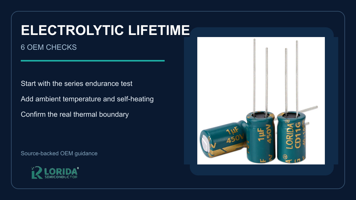
Start with the complete manufacturer series and case code. The endurance or load-life line belongs to a particular construction, voltage, capacitance, case size, temperature, and test method. It cannot be transferred to another series because the sleeve looks similar. Current Rubycon examples illustrate the range: the TLV chip series is listed at 105°C for 5,000 hours, the TRV series at 105°C for 5,000–10,000 hours, and the TGV series at 125°C for 3,000–5,000 hours. These figures are useful evidence only after the buyer locks the exact order code and approved datasheet.
End of life is a characteristic limit, not a timer
Liquid-electrolyte capacitors age as electrolyte is lost through the sealing system. Rubycon’s technical note describes the typical electrical trend as reduced capacitance and increased tangent of the loss angle, tan δ. That means the OEM must define which electrical limits matter to the circuit at the end of the required service period. A procurement statement such as “long life capacitor” is therefore incomplete. The RFQ should identify the allowable capacitance change, impedance or ESR condition, leakage-current requirement, and any application-specific margin.
Six checks for a defensible lifetime estimate
1. Lock the exact series, case, and endurance test
Record manufacturer, series, capacitance, rated voltage, case diameter and length, terminal style, category temperature, endurance hours, and the test conditions copied from the controlled datasheet. If the supplier offers a substitution, repeat the review instead of accepting a generic cross-reference. For LORIDA sourcing, buyers can begin with the radial aluminum electrolytic capacitor range, then request the applicable series sheet and drawing for the selected order code.
2. Measure ambient temperature where the capacitor operates
Use the air temperature adjacent to the capacitor under the worst credible equipment state, not the room temperature outside the enclosure. Include blocked filters, reduced fan speed, solar load, neighboring semiconductors, transformer heat, and normal manufacturing tolerances. Rubycon’s technical note states the familiar “10°C, two-times” relationship: estimated life doubles for each 10°C decrease. The same note reports good agreement with Arrhenius behavior in the 70–90°C range, but deviation below 60°C and above 105°C. Treat the equation as a model within the manufacturer’s stated limits, not as permission to extrapolate indefinitely.
3. Add ripple-current self-heating
Ripple current produces internal heating through impedance. Obtain the RMS current spectrum or a defensible worst-case measurement, then apply the series-specific frequency multipliers and thermal method. A single DC current value cannot replace this step. Rubycon’s automotive design guidance identifies ambient temperature and ripple-current self-heating as primary lifetime drivers and highlights internal-temperature measurement for severe environments. Confirm the result on hardware with the intended capacitor, PCB, busbar, and airflow.
4. Reproduce the real cooling boundary
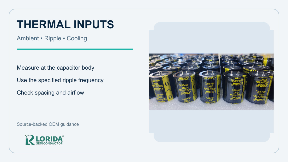
Spacing, orientation, airflow, copper area, clamp design, and nearby hot parts change the capacitor’s temperature. TDK’s general technical information notes that stated useful-life values normally assume natural cooling unless a datasheet says otherwise, and that impaired cooling can occur in closely packed capacitor banks. A calculation using free-air assumptions is not valid for a dense enclosed bank. Photograph the sample build, record thermocouple positions, and keep the steady-state temperature trace with the qualification file.
5. Check voltage, surge, and operating profile
Rated voltage is a ceiling under stated conditions, not a design target. Review the continuous DC voltage, ripple waveform, startup overshoot, regenerative events, shutdown discharge, series balancing, and abnormal conditions. Also define daily operating hours, standby temperature, starts per day, seasonal profile, and mission duration. A machine that runs eight hours per day and cools completely is thermally different from a continuously energized cabinet, even if their peak measurements match.
6. Validate the approved sample and preserve evidence
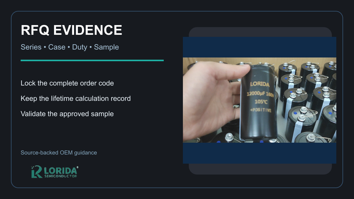
Use the calculation to choose candidates, then validate the real build. Measure body temperature after thermal equilibrium, verify polarity and vent clearance, inspect solder or terminal joints, and confirm electrical performance before and after stress. For larger cases, compare the snap-in capacitor and screw-terminal capacitor mechanical and thermal constraints. Retain the approved sample, order code, drawing revision, datasheet revision, test record, and deviation approvals.
What to put in the RFQ and qualification report
A compact comparison table
| Evidence item | Minimum RFQ input | Qualification output |
|---|---|---|
| Product identity | Full series, rating, case and terminals | Approved order code and drawing revision |
| Thermal duty | Local ambient, airflow, spacing and hot neighbors | Measured body-temperature trace |
| Electrical duty | DC voltage, ripple spectrum, surge and starts | Worst-case waveform and RMS calculation |
| Life model | Manufacturer equation and permitted range | Calculation sheet with assumptions |
| Release evidence | Datasheet, sample and acceptance limits | Signed sample report and change control |
Worked screening example without inventing a promise
Suppose a controlled datasheet states 5,000 hours at 105°C and the manufacturer allows the 10°C, two-times model for the actual series. A first screening calculation at 85°C produces 20,000 hours because the temperature is two 10°C steps lower. That number is not yet a warranted service life: it must still reflect ripple self-heating, cooling, voltage, the duty cycle, the equation’s permitted range, and the defined end-of-life limits. The safe procurement conclusion is “candidate passes the preliminary model, pending thermal validation,” not “the capacitor will last 20,000 hours.”
Key Takeaways
Six decisions to retain in the project file
Use the exact series endurance specification, not a generic 105°C label.
Measure local ambient temperature in the worst credible equipment state.
Include ripple-current self-heating with the manufacturer’s method.
Validate spacing, airflow, orientation, and neighboring heat sources.
Document voltage, surge, daily duty, and abnormal operating states.
Release only the approved sample and controlled evidence set.
Frequently Asked Questions
Does a 105°C, 5,000-hour capacitor last only 5,000 hours?
No; 5,000 hours is normally an endurance-test rating under defined datasheet conditions, not a direct field-life deadline. The real estimate depends on the exact series formula, actual capacitor temperature, ripple-current heating, cooling, voltage, duty cycle, and end-of-life criteria. Lower temperature often increases the estimate, but extrapolation must stay within the manufacturer’s permitted method and range. Ask the supplier for the controlled datasheet and calculate from measured conditions in the intended equipment rather than from the sleeve marking alone.
Can I use the 10°C rule for every aluminum electrolytic capacitor?
No; use the 10°C rule only when the manufacturer applies it to the exact capacitor series and operating range. Rubycon documents a two-times relationship for each 10°C decrease but also notes deviation outside parts of the temperature range. Polymer and hybrid constructions may use different models, and even liquid-electrolyte series can impose correction factors or maximum calculated life. Record the source equation, its limits, and every temperature input so another engineer can reproduce the estimate.
Which temperature should be entered in a lifetime calculation?
Use the temperature defined by the manufacturer’s equation, supported by measurements on the real assembly. Depending on the method, this may combine local ambient temperature with a calculated or measured internal rise from ripple current. Room temperature outside the enclosure is rarely sufficient. Measure after thermal equilibrium under the worst credible load, cooling, spacing, and neighboring-component conditions, and document sensor placement. If the method requires core temperature that cannot be measured directly, follow the manufacturer’s validated thermal procedure.
What should a buyer request before approving an alternate capacitor?
Request the complete order code, controlled datasheet, drawing, endurance definition, ripple-current data, lifetime equation, and a sample for the actual build. Compare rated voltage, capacitance, case size, terminals, impedance or ESR, ripple frequency multipliers, category temperature, vent clearance, and qualification limits. Then repeat the thermal and electrical checks with the alternate installed. A generic cross-reference or matching capacitance and voltage is not sufficient evidence because construction, thermal resistance, and life-model limits can differ.
Last Updated: October 12, 2026. Technical review: LORIDA engineering content team. Sources: Rubycon Aluminum Electrolytic Capacitor Technical Notes and product-series pages; Rubycon automotive design guidance; TDK General Technical Information for Aluminum Electrolytic Capacitors. Manufacturer source documents govern. For an application review, contact LORIDA with your waveform, temperature, duty cycle, case constraints, and required service period.