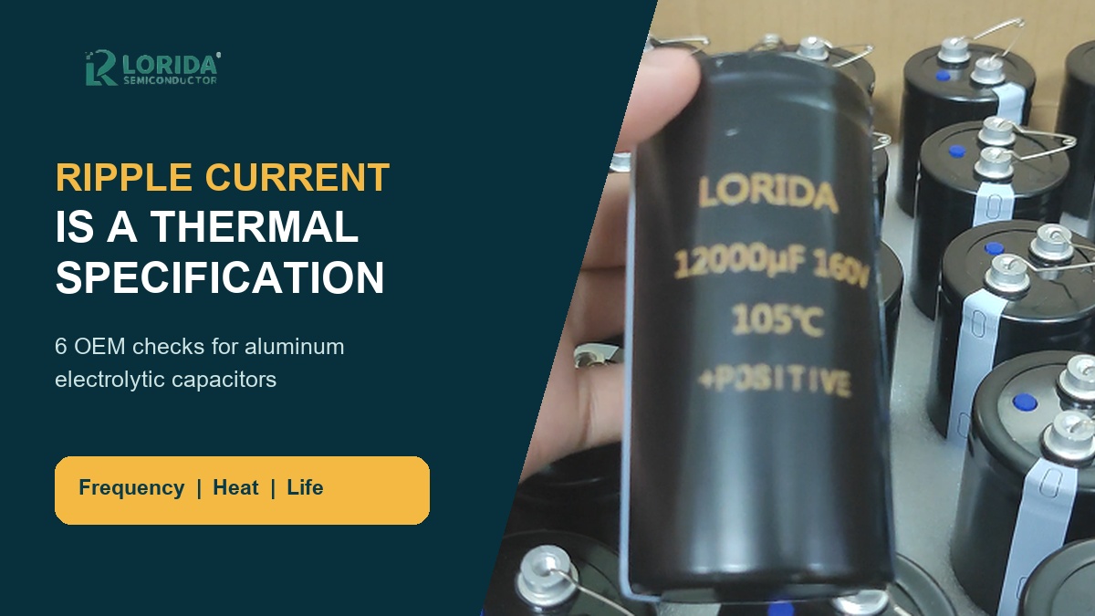
Electrolytic capacitor ripple current must be verified at the real frequency spectrum, ambient temperature and cooling condition, not copied from a catalogue headline. Ripple current produces internal heating through impedance, and that temperature rise influences useful life. The safe OEM workflow is to normalize each current component with the exact series frequency factor, combine the components, compare the result with the rated condition, then measure temperature in the real assembly. This guide turns that workflow into six RFQ and sample checks.
Key Takeaways
What the RFQ must contain
RMS ripple current by frequency, not one unqualified ampere value.
Maximum ambient temperature, airflow and nearby heat sources.
The exact capacitor series and its frequency and temperature coefficients.
Capacitor-bank sharing assumptions and the test point for temperature rise.
Measured current spectrum, case temperature and bus-voltage waveform.
Why Does Ripple Current Need Frequency Data?
The catalogue value has a stated test condition
Manufacturers publish ripple current at defined frequencies and temperatures because capacitor impedance changes with frequency and temperature. TDK states that data sheets specify the maximum permissible ripple current at the upper category temperature, while additional values may be provided below that temperature for comparison (TDK general technical information). An RFQ that says only "10 A ripple" cannot be compared with a data-sheet rating unless the waveform, frequency basis and thermal condition are also known.
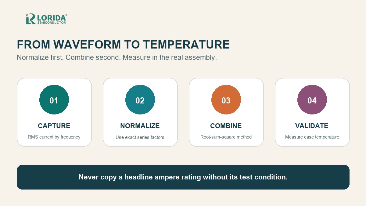
Normalize each frequency component before combining
TDK gives a worked example with 34.2 A RMS at 300 Hz and 12.4 A RMS at 3 kHz. Using series-specific frequency factors of 1.12 and 1.17, the equivalent 100 Hz components become 30.5 A and 10.6 A. Root-sum-square combination gives 32.3 A, not the simple arithmetic sum (TDK worked example). These numbers demonstrate the method only; use the factors for the exact offered series.
How Should OEMs Check the Thermal Result?
Current ratio affects temperature rise approximately by the square
Nichicon expresses capacitor temperature rise as delta Tn = (In / Io)^2 x delta To and notes an approximate 5 deg C temperature rise for a 105 deg C snap-in type at the referenced rated condition. It also recommends thermocouple measurement because ESR changes with temperature and actual waveforms contain multiple frequency components (Nichicon CAT.8101H). The practical lesson is straightforward: a current increase can create a disproportionately larger thermal penalty, so the sample must be tested in its real enclosure.
Cooling assumptions belong in the specification
TDK explains that useful-life data normally assume natural cooling unless a data sheet states otherwise. Forced air or a heat sink may improve permissible load, while close packing, thermally insulating sealing or vacuum can reduce cooling and useful life. Record capacitor spacing, mounting orientation, airflow, heat-sink contact and nearby components. For a bank, measure more than one unit because current and temperature may not divide equally.
Which Catalogue Numbers Can Be Compared?
Keep temperature, frequency and series in the same row
A TDK catalogue example, B43654B5477M060, is listed as 470 uF, 450 V DC, 35 x 40 mm and more than 5,000 h rated useful life. Its listed ripple values differ by condition: 2.05 A at 100 Hz and 105 deg C versus 3.57 A at 100 Hz and 85 deg C (TDK product catalogue). This is not a LORIDA rating; it shows why buyers must keep the condition beside the number.
Use a condition-aware comparison table
| RFQ field | Required evidence | Reject when |
|---|---|---|
| Ripple spectrum | RMS current at each significant frequency | Only one unqualified current value is supplied |
| Frequency conversion | Coefficient table for the exact series | A generic coefficient is copied across series |
| Thermal condition | Ambient, airflow, spacing and mounting | The catalogue temperature is treated as the equipment ambient |
| Lifetime basis | Series-specific curve or calculator inputs | A rule of thumb is presented as a guarantee |
| Sample validation | Waveform, case temperature and test duration | No measurement point or acceptance limit is defined |
What Should the Sample Test Record?
Measure the waveform before judging the capacitor
Capture DC-bus voltage, RMS ripple current and the dominant spectral components at worst-case line and load. Record probe bandwidth, sampling method and whether the measurement represents one capacitor or the full bank. Then compare the normalized equivalent current with the exact series rating. TDK's worked example compares 32.3 A equivalent current with a 17 A reference rating, producing a factor of 1.9; at 55 deg C, the cited series curve indicates 100,000 h. Do not transfer that result to another series.
Close the loop with temperature and inspection
Measure case temperature at a repeatable location after thermal stabilization and document airflow and adjacent heat sources. Compare units across the bank, inspect terminal torque and mounting, and repeat the test after any enclosure or fan change. Buyers evaluating a high-voltage assembly can also review LORIDA's screw-terminal capacitor range, the 1000 uF 450 V example page and the related VFD DC-bus selection guide.
Frequently Asked Questions
Buyer questions before an RFQ
Can I use the ripple-current value from a different frequency?
No, not without the exact series frequency coefficient. Convert every significant RMS current component to the data sheet's reference frequency using the coefficient table for that capacitor series. Combine the converted components by root-sum-square when the manufacturer method requires it. Do not use a coefficient from another series simply because capacitance and voltage are similar. The dielectric system, foil design, electrolyte, ESR and thermal construction may differ. Send the supplier the measured spectrum as well as the total RMS current so the conversion can be checked and reproduced.
Does a lower ambient temperature always guarantee longer life?
A lower ambient temperature usually helps, but it does not by itself guarantee the required life. Internal heating from ripple current, restricted airflow, nearby heat sources and bank spacing can raise capacitor temperature above the measured equipment ambient. Manufacturer life curves and calculators also apply to named series and defined load conditions. Record both ambient and capacitor case temperature, then use the exact series guidance. Treat the result as an engineering estimate unless the supplier explicitly provides a contractual life statement for the offered part and application.
How do I test current sharing in a capacitor bank?
Measure individual branch current or individual capacitor temperature under the worst repeatable operating condition. A bank total can hide unequal sharing caused by wiring impedance, busbar geometry, tolerance, ESR variation or cooling differences. Use comparable sensors and measurement points on multiple units, record the stabilized temperatures, and investigate outliers. Include the busbar layout, cable lengths, balancing components and mounting drawing in the RFQ. If the design changes spacing, conductor geometry or airflow, repeat the test because the current and thermal distribution may change.
What should an OEM send for a ripple-current sample review?
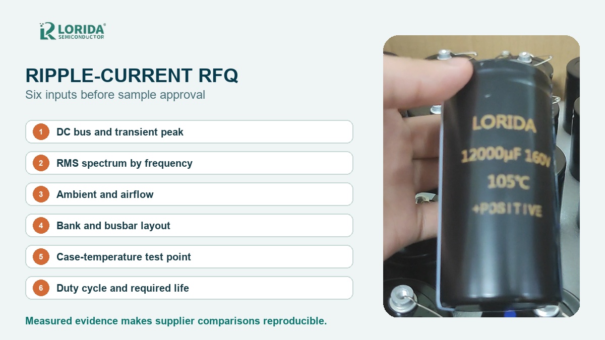
Send the maximum DC voltage, capacitance target, current spectrum, ambient range, cooling arrangement, mechanical envelope and required service profile. Add the expected duty cycle, bank connection, precharge or discharge behavior, terminal and mounting drawing, and the acceptance method for temperature rise. If possible, attach oscilloscope captures with probe and bandwidth information. This package lets the supplier identify missing data before recommending a candidate. A voltage-and-capacitance request alone cannot establish ripple capability, useful life or mechanical suitability.
Prepare a Reproducible Ripple-Current RFQ
Send the waveform and thermal conditions
Share the six inputs and your mechanical drawing. LORIDA can review the application package and identify candidate aluminum electrolytic capacitor constructions for sample validation.
Send Your Capacitor RequirementsSources
Primary technical references
TDK, Aluminum Electrolytic Capacitors - General Technical Information.
Nichicon, Application Guidelines for Aluminum Electrolytic Capacitors, CAT.8101H.
TDK aluminum electrolytic capacitor product catalogue.
Last Updated: September 23, 2026. Exact values in this article are source examples and must not be treated as ratings for a different capacitor series.