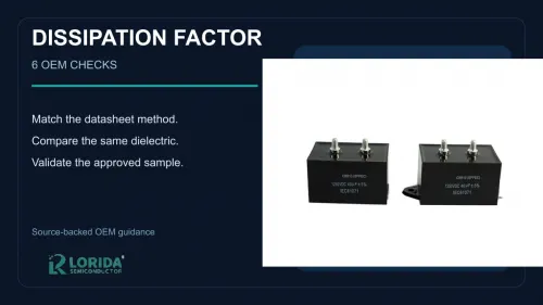
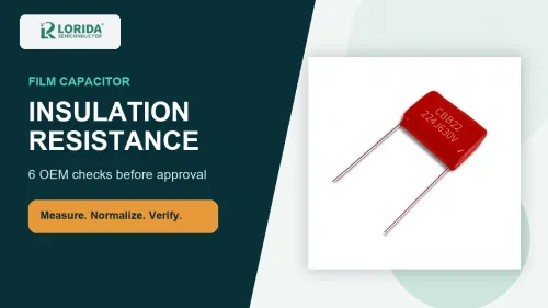
A film capacitor's dissipation factor is only meaningful when the dielectric, capacitance, frequency, test voltage, temperature, and acceptance limit are stated together. TDK identifies 1 kHz as the standard measuring frequency and notes additional 10 kHz or 100 kHz measurements for some MKT, MFP, and MKP parts at 1 µF or below. This guide gives OEM buyers six checks for comparing quotations, approving samples, and detecting test-method mismatches before a production order.
Key Takeaways
What the buyer should require
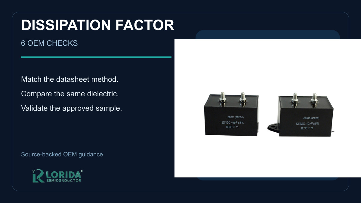
Do not compare tan δ values unless the frequency, temperature, voltage, and capacitance range match.
Confirm the dielectric family. Polypropylene and polyester do not have the same loss behavior.
Ask whether the stated number is a dielectric value, a complete-capacitor value, or a post-test change.
Use the approved sample and ordered code as the acceptance reference; a family name alone is not enough.
Evaluate loss with ripple current, ESR, cooling, and hot-spot temperature rather than as an isolated catalog number.
What Dissipation Factor Actually Describes
The ratio links loss to capacitive reactance
Dissipation factor, commonly written as tan δ, expresses the loss angle of a capacitor under sinusoidal AC conditions. TDK's power-capacitor glossary defines it as the ratio of equivalent series resistance to capacitive reactance. Because capacitive reactance changes with frequency, the same component cannot be assigned one context-free number for every test and application. The complete measurement condition belongs beside the result.
For frequencies well below self-resonance, TDK separates tan δ into parallel, series, and dielectric components. The parallel component depends on insulation resistance. The series component rises with series resistance, frequency, and capacitance. The dielectric component represents polarization loss. TDK gives approximately 10-4 as a typical dielectric-loss level for polypropylene, while polyester is described as higher and more frequency-dependent. This is why an OEM comparison must identify the dielectric rather than treating all film capacitors as interchangeable.
Loss becomes heat in the application
The number matters because electrical loss becomes temperature rise. TDK's B3237*F technical guide gives ESR = tan δ/(ωC), where ω is angular frequency and C is capacitance. It also states that power loss can be evaluated as I²ESR for each relevant frequency. A low bench reading does not automatically prove safe service when the actual ripple-current spectrum, mounting, cooling, and ambient temperature differ from the test setup.
Six OEM Checks Before Comparing Values
1. Confirm dielectric and construction
Start with a precise construction description: metallized polypropylene, polyester, foil, or another defined system. IEC 60384-16:2019 covers fixed metallized polypropylene dielectric DC capacitors and remains the current edition with a stability date of 2030. Its scope does not automatically cover every AC, pulse, suppression, or motor-run part. Ask the supplier to link the quoted limit to the exact series specification, ordered code, and applicable standard.
2. Match capacitance and measurement frequency
TDK states that 1 kHz is the standard measuring frequency for film-capacitor dissipation factor. For MKT, MFP, and MKP capacitors at or below 1 µF, additional 10 kHz or 100 kHz measurements may be used. Those exact frequencies are not interchangeable. A quotation that says only “low loss” or “tan δ max” without frequency is incomplete. Record capacitance and frequency on the sample report and confirm the LCR meter was configured accordingly.
3. Record test voltage and temperature
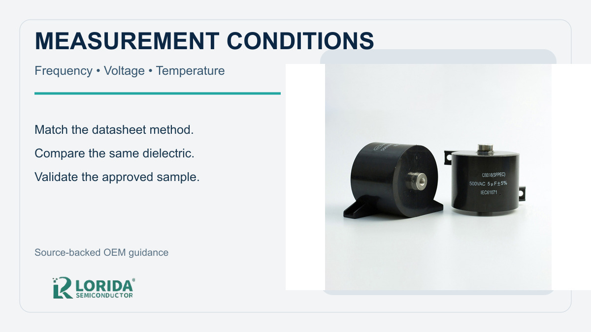
Test signal level and temperature can change the result or make two reports non-comparable. Require the AC test voltage, any DC bias, stabilization time, ambient temperature, and instrument model. If the product specification defines a conditioning period, follow it. Do not replace a series-specific method with a purchasing department's convenient default. When re-testing incoming samples, use the same method as the supplier's approved report.
4. Separate initial limits from change limits
An initial maximum and a change after endurance or damp heat answer different questions. TDK's published heavy-duty B3293* X2 example uses 85 °C and 85% relative humidity for 1,000 or 2,000 hours and reports a post-test dissipation-factor change limit of no more than 5 × 10⁻³ at 1 kHz. That value belongs to the named series and test, not every film capacitor. Ask the RFQ to distinguish initial tan δ, post-test Δtan δ, test duration, voltage, and recovery conditions.
5. Relate the value to ESR and thermal duty
Use the loss number in a thermal calculation or validation plan. Collect RMS current by frequency, switching or fundamental frequency, ambient temperature, enclosure airflow, mounting surface, and permitted hot-spot temperature. TDK's B32377G announcement, for example, identifies a tan δ range of 0.7 to 1.2 × 10⁻³ for that specific three-phase AC-filter series. It illustrates how values must stay tied to a named design and duty rather than becoming a universal purchasing limit.
6. Define sample and production acceptance evidence
Require a traceable report for the approved sample and a practical incoming-inspection plan. The report should show ordered code, lot or date code, sample quantity, instrument, calibration status, fixtures, conditions, individual readings, limit, and disposition. For production, define whether every lot, a sampling plan, or a periodic audit applies. Keep the golden sample and measurement method under revision control so a supplier change cannot silently alter the baseline.
| RFQ field | Required evidence | Why it matters |
|---|---|---|
| Dielectric / construction | Exact series and ordered code | Loss behavior differs by material and construction |
| Capacitance and frequency | Nominal C and stated test frequency | Tan δ is frequency-dependent |
| Voltage and temperature | AC level, bias, ambient, stabilization | Prevents incompatible comparisons |
| Acceptance limit | Initial max or post-test change | These are different controls |
| Thermal duty | RMS spectrum, cooling, hot-spot target | Connects bench loss to application heat |
| Traceability | Lot, instrument, fixture, raw readings | Supports repeatable approval and audits |
How to Turn the Check Into an RFQ
Send operating data, not a copied catalog phrase
Begin with the circuit role, waveform, voltage, RMS current spectrum, ambient range, cooling, space, terminals, lead pitch, and applicable qualification. Then request the supplier's exact method and series limit. Compare candidates within the same dielectric and condition set. LORIDA's film capacitor category can be used to identify relevant constructions, while a specific record such as the CBB22 4.7 µF 630 V page shows the product-record level that should be confirmed before sampling.
Do not infer an unlisted tan δ limit from capacitance, voltage, package color, or a neighboring series. Ask for the ordered-code datasheet and approved-sample report. If your project needs a technical comparison, send the conditions through the LORIDA contact page and request a candidate review without assuming suitability, compliance, lead time, or lifetime before engineering validation.
Frequently Asked Questions
What is a good dissipation factor for a film capacitor?
A good value is one that meets the exact series limit under the specified measurement conditions and thermal duty. There is no responsible universal maximum for every film capacitor. Polypropylene typically has lower dielectric loss than polyester, while capacitance, frequency, contacts, and construction affect the complete-capacitor value. Compare only parts measured at the same frequency, voltage, and temperature, and require the supplier to identify whether the limit is an initial maximum or a change after a defined test.
Why can two suppliers report different tan δ values?
Different dielectric, capacitance, frequency, signal level, temperature, fixtures, and acceptance definitions can all produce different reports. One supplier may quote a dielectric value while another reports the complete capacitor. One may measure at 1 kHz while another uses 10 kHz. The correct response is to normalize the method, not automatically select the smaller number. Put the complete condition set in the RFQ and repeat it during incoming inspection.
Is dissipation factor the same as ESR?
No, but they are directly related at a specified frequency and capacitance. For a simplified capacitor model, TDK gives ESR = tan δ/(ωC). ESR is expressed in ohms, while tan δ is dimensionless. Because ω and C appear in the relationship, a tan δ value cannot be converted to ESR without frequency and capacitance. At high frequency or near resonance, parasitic inductance and the actual impedance model also matter.
Should incoming inspection use 1 kHz?
Use 1 kHz only when it matches the applicable datasheet or approved method. TDK identifies 1 kHz as the standard film-capacitor measurement frequency but also notes 10 kHz or 100 kHz for some MKT, MFP, and MKP capacitors of 1 µF or less. The ordered-code specification should control. Record the instrument, fixture, voltage, temperature, and stabilization so the production check remains reproducible.
Sources
Primary technical references
TDK Electronics, Film Capacitors — General Technical Information.
TDK Electronics, B3237*F Power Electronic Capacitors — General Information.
IEC, IEC 60384-16:2019.
TDK Electronics, Reliable When It Is Hot and Humid.
TDK Electronics, B32377G AC Filter Capacitor Announcement.
Last Updated: October 11, 2026