Film capacitor insulation resistance must be evaluated with the test voltage, reading time, temperature, humidity, and capacitance stated together. A resistance value by itself is not comparable because the result changes with environment and because larger capacitance is often specified by an insulation time constant. This OEM guide gives six checks for RFQs, incoming inspection, and first-article approval without turning one supplier's series limit into a universal rule.
Key Takeaways
What an OEM team should remember
Define voltage, reading time, temperature, humidity, and acceptance limit in the same test clause.
For larger capacitance, compare the insulation time constant, τ = Rins × CR, when the datasheet uses that format.
Condition samples and record ambient conditions before comparing suppliers.
Use series-specific datasheets and first-article evidence; never assume one published limit applies to every film construction.
Investigate humidity exposure, surface contamination, fixture leakage, and stabilization time before rejecting a batch.
What Film Capacitor Insulation Resistance Means
It is a controlled leakage measurement, not an isolated catalog number
Insulation resistance, commonly written as Rins or IR, expresses how strongly the dielectric and construction oppose DC leakage after a specified voltage has been applied. The fixture, surface cleanliness, lead spacing, test voltage, charge duration, and reading delay all influence the measured current. TDK's general technical information defines the insulation time constant as τ = Rins × CR. This lets engineers compare capacitors with different capacitance values when the series specification is expressed in seconds.
Published examples show why the test clause matters. TDK's B32701P/B32703P series lists a minimum insulation time constant of 10,000 s measured at 100 V, 20°C, and relative humidity no higher than 65% in the as-delivered condition. That is a series-specific reference, not a promise for every film capacitor. Another TDK MKP series uses 30 GΩ for capacitance at or below 0.33 µF and 10,000 s above that boundary, demonstrating why the unit and capacitance range must be preserved.
Six OEM Checks Before Approval
Checks 1-2: define the electrical method
Test voltage: State the DC voltage and polarity. Do not substitute a hipot value for the IR measurement voltage. For example, the B32701P/B32703P datasheet separately lists a DC test voltage of 1.4 × VR for 2 seconds; that withstand test is not the same as its IR test at 100 V.
Reading time: State when the current or resistance is read after applying voltage. Dielectric absorption means a reading taken immediately can differ from one taken after stabilization. Use the timing in the applicable component standard or series datasheet.
Checks 3-4: normalize the environment and result
Temperature and humidity: Record both. TDK notes that insulation resistance is temperature-dependent and that humidity significantly reduces it. Comparing two suppliers under different conditions is not a valid qualification.
Correct metric: Record MΩ, GΩ, or seconds exactly as specified. When τ is required, calculate it from the measured Rins and rated capacitance in consistent units. Keep raw readings so the calculation can be audited.
Checks 5-6: verify the sample and acceptance evidence
Sample condition: Identify as-delivered, preconditioned, post-humidity, or post-endurance status. TDK describes reversible moisture effects below 93% RH for limited exposure, while long exposure can create irreversible changes.
Acceptance evidence: Require the series datasheet, lot traceability, calibrated instrument ID, fixture information, ambient record, individual values, and disposition. A certificate with only “PASS” cannot explain drift or support a later failure analysis.
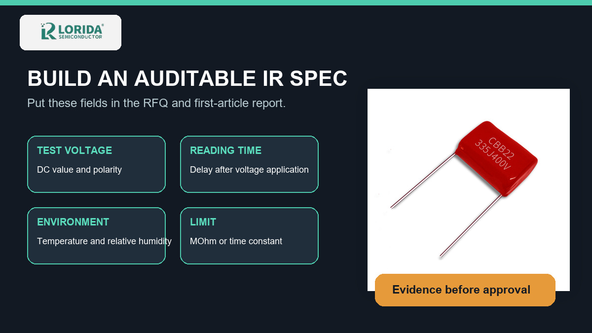
RFQ and Incoming Inspection Table
Use a structured clause that suppliers can answer consistently
| Field | What to specify | Evidence to retain |
|---|---|---|
| Voltage | DC value and polarity | Test setting and procedure |
| Time | Charge and reading delay | Timestamped raw values |
| Environment | Temperature and RH range | Ambient log |
| Limit | MΩ/GΩ or τ in seconds | Datasheet revision |
| Sampling | Quantity and lot rule | Serial/lot mapping |
Humidity and Temperature Change the Decision
Use accelerated tests as construction-specific evidence
Humidity qualification is valuable only when its severity and pass criteria are explicit. A TDK MKP example uses 1,000 hours at 40°C and 93% RH with rated DC voltage; its post-test criteria include capacitance change no greater than 5%, dissipation-factor change no greater than 0.002 at 1 kHz, and insulation resistance at least 200 MΩ. Panasonic's ECHU(X) example lists 1,000 hours at 40°C and 90-95% RH with post-test IR of at least 1,000 MΩ. These are different product examples with different criteria, so an OEM should use the actual proposed series specification.
Temperature limits also remain series-specific. The B32701P/B32703P example allows operation up to 110°C and applies voltage derating of 0.62% per °C above 85°C. Such data belongs in design verification, but it must not be copied onto a different construction without written evidence.
First-Article Validation Workflow
Connect the catalog claim to the delivered lot
Begin with the proposed film capacitor family and the exact series drawing. Confirm capacitance, voltage, dimensions, lead spacing, dielectric construction, and application duty before writing the IR clause. For radial metallized polyester requirements, review the CBB22 capacitor options, then send the final electrical and environmental requirements to engineering rather than selecting from appearance alone.
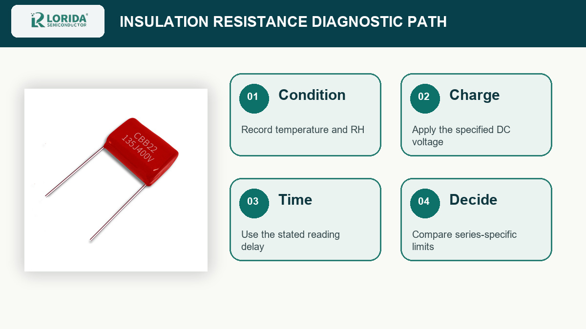
Condition the samples, clean and verify the fixture, record ambient temperature and RH, apply the specified DC voltage, wait the defined interval, and save individual readings. If a result is unexpectedly low, repeat only after checking instrument range, fixture leakage, surface contamination, moisture exposure, and recovery conditions. Pair IR with capacitance and dissipation factor so that the decision reflects the component's overall condition. For dielectric damage and recovery behavior, see the companion guide on film capacitor self-healing checks.
Frequently Asked Questions
What insulation resistance is acceptable for a film capacitor?
The acceptable value is the limit in the applicable series datasheet or approved drawing under its stated test conditions. There is no single value that safely covers every capacitance, dielectric, voltage rating, package, and environment. Some datasheets specify resistance in MΩ or GΩ for smaller capacitance and an insulation time constant in seconds for larger values. The RFQ should therefore name the series, capacitance range, DC test voltage, reading delay, temperature, humidity, sample condition, and pass limit. If a supplier quotes only a resistance number, ask for the complete method before treating it as comparable evidence.
Why does insulation resistance decrease in humid conditions?
Humidity can reduce insulation resistance because absorbed moisture and surface films create additional leakage paths. The magnitude and recovery depend on the coating, case, sealing, exposure time, temperature, contamination, and dielectric system. TDK notes that moisture absorption and desorption time constants can range from roughly half a day for uncoated parts to several weeks for plastic cases. That is why incoming inspection should not compare a recently exposed sample with a conditioned reference. Record storage history, stabilize samples under the agreed conditions, and use the series-specific humidity qualification rather than inventing a universal correction factor.
Should I compare resistance or the insulation time constant?
Use the metric specified by the component series, and use the insulation time constant when capacitance-normalized comparison is required. The time constant is calculated as τ = Rins × CR, so it accounts for rated capacitance while retaining the leakage information. This is useful because the same absolute resistance can represent different behavior at different capacitance values. Keep the original resistance, capacitance, units, voltage, reading time, temperature, and humidity in the report; do not store only the calculated seconds. A normalized figure improves comparison, but it does not replace the datasheet's construction-specific acceptance criteria.
Can a low reading prove the dielectric is defective?
No, one low reading does not by itself prove that the dielectric is defective. First exclude fixture leakage, wrong test voltage, insufficient charging time, contamination, moisture, damaged leads, and an instrument range problem. Then condition and retest only under the approved procedure while preserving the original result. If capacitance or dissipation factor has also shifted, or if the low value persists after environmental recovery, escalate the sample for construction review. The final disposition should reference the approved series limit and lot evidence, not an informal comparison with a different capacitor family.
Sources and Next Step
Verified technical references used in this guide
Technical data points were checked against TDK Film Capacitors General Technical Information, TDK B32701P/B32703P and B3267*P series documents, Panasonic ECHU(X) specifications, and TDK's robust MKP humidity article. Values are attributed examples, not LORIDA-wide guarantees.
Send capacitance, voltage, waveform, temperature, humidity, dimensions, and the required IR method. Send your requirements
Last Updated: October 8, 2026