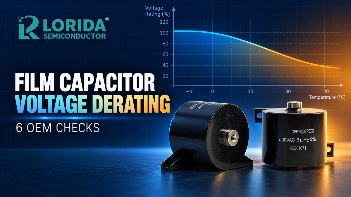
Film capacitor voltage derating means reducing the allowed operating voltage when temperature, frequency, ripple current, or transient stress makes the nameplate voltage insufficient by itself. A correct OEM check uses the exact series data sheet and the complete waveform. For example, one Panasonic film-capacitor series specifies a 1.25% per degree C reduction above 85 deg C for its 450 VDC version, while a different Panasonic power-film series begins derating voltage and current above 70 deg C. These are series-specific examples, not universal LORIDA limits.
Last Updated: 2026-10-21
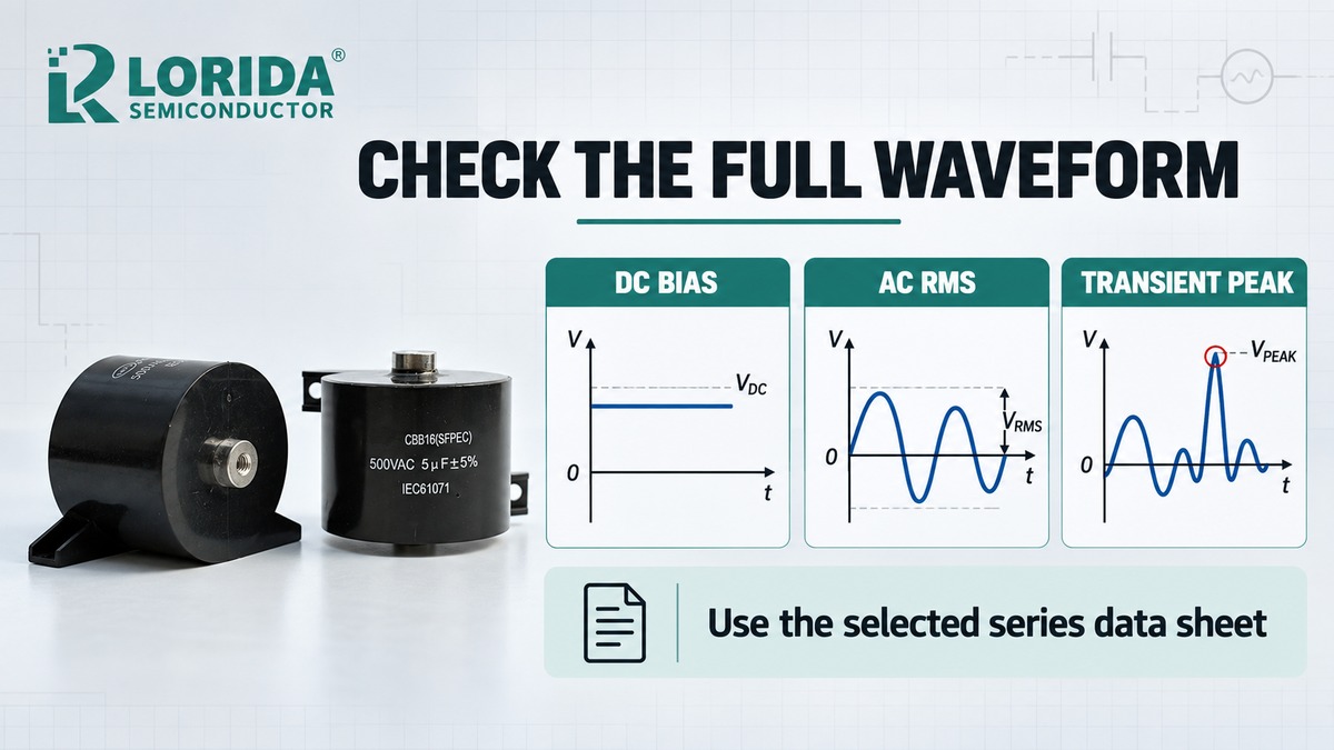
Rated voltage is only the starting point; verify DC bias, AC RMS voltage, peak-to-peak swing, transient peaks, temperature, and frequency together.
Never copy a derating percentage from another dielectric, construction, or manufacturer series.
Use capacitor surface or hot-spot temperature where the data sheet requires it, not only cabinet ambient.
Confirm RMS current and self-heating separately from voltage.
Release a replacement only after real waveform and thermal sample testing.
Why the Rated Voltage Is Not the Whole Answer
DC, AC, and transient limits describe different stresses
A film capacitor can see a DC offset, an alternating component, switching edges, and occasional overshoot in the same application. The voltage printed on the body does not automatically define every one of those limits. Panasonic's EZPE documentation, for example, states that the part is designed for DC use, requires the peak voltage to remain within the rated voltage, and limits peak-to-peak voltage to 0.2 times the rated voltage for that cited series. TDK's film-capacitor technical information separately explains that permissible AC voltage can be limited by dielectric loss at one frequency range and by current-handling capability at a higher range.
Sources: Panasonic EZPE series information; TDK Film Capacitors: General Technical Information.
Temperature changes the permissible operating point
Temperature derating must follow the selected series. Panasonic's ECW-F(E) sheet lists a category range of -40 deg C to +105 deg C. It states 1.25% per degree C voltage derating above 85 deg C for the 450 VDC version and 1.0% per degree C above 85 deg C for the 630 VDC version. Another Panasonic power-film document begins voltage, RMS-current, and peak-current derating when capacitor surface temperature exceeds 70 deg C. TDK defines operating temperature as ambient temperature plus self-heating and requires that sum to remain at or below the upper category temperature. These different thresholds demonstrate why a general company rule cannot replace a part-number data sheet.
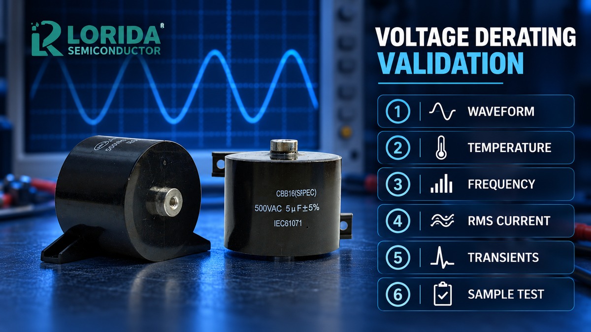
Six OEM Checks Before Selecting a Voltage Margin
1. Capture the complete voltage waveform
Measure the capacitor terminals under the worst credible operating conditions. Record maximum continuous DC bias, AC RMS voltage, peak voltage, peak-to-peak voltage, switching frequency, startup overshoot, regenerative events, and fault-recovery behavior. Do not calculate margin from nominal bus voltage alone. A short transient can determine the required series even when the average voltage looks comfortable. State probe bandwidth, measurement location, grounding method, operating mode, and sample rate so the supplier can judge whether the waveform evidence is meaningful.
2. Use the correct temperature point
Record the maximum ambient near the capacitor and the measured capacitor surface temperature after thermal stabilization. TDK writes the relationship as operating temperature equals ambient temperature plus self-heating. If the series chart uses surface temperature, an enclosure ambient reading is not an equivalent input. Include airflow, neighboring heat sources, mounting orientation, altitude, and duty cycle. For a multi-mode product, evaluate every mission-profile segment rather than reporting only the room-temperature laboratory condition.
3. Check the series-specific DC derating curve
Map the measured peak or continuous voltage to the manufacturer's curve at the measured temperature. Do not assume that every polypropylene film capacitor uses the same slope or threshold. The Panasonic examples above use different rules above 85 deg C, while its EZPE documentation starts a different derating process above 70 deg C. If the proposed LORIDA code does not yet have a controlled derating curve, keep the design pending and request the applicable specification instead of inventing a percentage.
4. Check AC voltage and RMS current versus frequency
Voltage derating does not prove that ripple heating is acceptable. TDK notes that maximum AC voltage varies with frequency and that high-frequency regions can be limited by dielectric loss or maximum current through the connection between the sprayed metal and film metallization. Obtain the harmonic spectrum or a conservative equivalent RMS current, then compare it with the selected series curves. The TDK CLARA tool can simulate up to four part numbers and up to five load conditions, but TDK still recommends real application tests close to the limits.
5. Separate repetitive stress from exceptional transients
Classify each event by amplitude, duration, repetition rate, source impedance, and energy. Repetitive switching overshoot belongs in the normal mission profile; a rare surge may use a different qualification limit. Ask whether the data sheet value is continuous, repetitive peak, non-repetitive peak, test voltage, or proof voltage. Panasonic's ECW-F(E) sheet, for example, specifies a terminal withstand test of 150% of rated DC voltage for 60 seconds. That is a test condition for that series, not permission to operate continuously at 150%.
6. Validate samples in the real assembly
Use instrumented samples at minimum and maximum line, full load, startup, shutdown, overload, and the hottest credible environment. Record terminal voltage, RMS current, capacitor surface temperature, and abnormal acoustic or mechanical behavior. Inspect capacitance, dissipation factor, insulation resistance, and appearance before and after the agreed test. TDK specifically recommends real application testing of temperature, current, voltage, and waveforms when conditions are near a limit. Sample validation does not replace qualification, but it can expose an incorrect waveform assumption before production.
| RFQ field | Evidence to provide | Supplier decision |
|---|---|---|
| Continuous DC bias | Maximum measured value by operating mode | Rated or category-voltage check |
| AC component | RMS voltage and frequency spectrum | Permissible AC-voltage curve |
| Ripple current | RMS current by frequency | Current limit and self-heating review |
| Transient stress | Peak, duration, repetition, source impedance | Repetitive or non-repetitive limit |
| Thermal condition | Ambient, surface temperature, airflow | Temperature derating and hot-spot margin |
| Validation plan | Modes, duration, measurements, acceptance criteria | Sample and qualification proposal |
How Buyers Should Compare Candidate Film Capacitors
Compare controlled conditions, not isolated catalog numbers
Place every candidate against the same waveform, temperature, cooling, and life target. A higher voltage label can still be unsuitable if the package cannot carry the ripple current or if its AC-voltage curve falls below the application point. Conversely, automatically choosing the highest voltage can add size and cost without resolving a thermal or frequency problem. Use the LORIDA 4.7 uF 630 V CBB22 product record as a sourcing starting point, then confirm the ordered code, waveform, temperature, drawing, and approved sample.
Keep safety-capacitor applications separate
TDK warns that standard film capacitors are generally not suitable for direct connection to public power networks and directs designers to purpose-built EMI suppression capacitors. Therefore, a voltage value alone cannot convert a general film capacitor into an X- or Y-class safety capacitor. If the part is across the line or line-to-earth, specify the required safety class, standard, approvals, impulse category, and certified series. For high-voltage pulse and resonant work, review a suitable construction such as the LORIDA CBB81 high-voltage film-capacitor record, with final approval tied to the actual duty.
Frequently Asked Questions
How much should I derate a film capacitor?
Use the exact manufacturer's curve for the selected series; there is no universal film-capacitor derating percentage. The required margin changes with dielectric, construction, temperature, DC bias, AC voltage, frequency, ripple current, transient profile, and life objective. One Panasonic series reduces its 450 VDC rating by 1.25% per degree C above 85 deg C, while another Panasonic power-film series begins voltage and current derating above 70 deg C. Those values illustrate the method only. Send the supplier the complete waveform and thermal profile, then request the controlled curve and confirm the design with sample testing.
Can I use a DC-rated film capacitor on AC?
Only when the selected series explicitly provides a permissible AC-voltage and current limit for the application's frequency and waveform. A DC rating is not automatically an AC RMS rating. AC operation adds dielectric losses and ripple current, and the limiting mechanism can change with frequency. Panasonic directs users of certain DC-rated parts to a separate permissible AC-voltage chart. TDK also describes frequency regions limited by dielectric loss and current handling. For direct mains connection, use the correct safety-approved suppression-capacitor class rather than a general DC film capacitor.
Should temperature derating use ambient or capacitor surface temperature?
Use the temperature definition stated by the series data sheet, and measure both ambient and capacitor surface temperature during validation. TDK defines capacitor operating temperature as ambient plus self-heating, while Panasonic power-film documentation applies derating when capacitor surface temperature exceeds a stated threshold. Cabinet ambient alone can miss heat from ripple current, adjacent semiconductors, restricted airflow, or enclosure radiation. Document sensor position, stabilization time, airflow, line and load condition, and the hottest mission-profile mode so the supplier can reproduce the decision.
Does a larger voltage rating guarantee longer life?
No; a larger voltage rating may increase electrical margin, but it does not by itself guarantee acceptable life. Life also depends on temperature, self-heating, RMS current, frequency, transient repetition, metallization, contact construction, humidity, mechanical integration, and the manufacturer's qualification model. A larger part can still run too hot when ripple current or cooling is wrong. Compare candidates under the same mission profile, verify the relevant curves, and test the actual assembly. TDK's CLARA tool can estimate limits and safety margins, but TDK still recommends real application testing near the limits.
Send LORIDA the waveform, temperature profile, ripple spectrum, transient definition, dimensions, and validation criteria through the contact page. Final limits remain subject to the ordered series specification and approved sample.