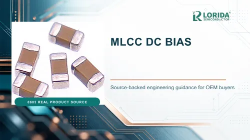
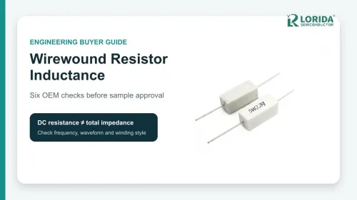
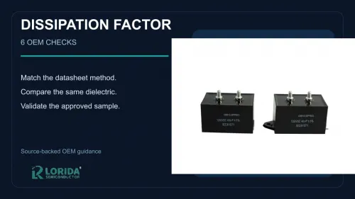
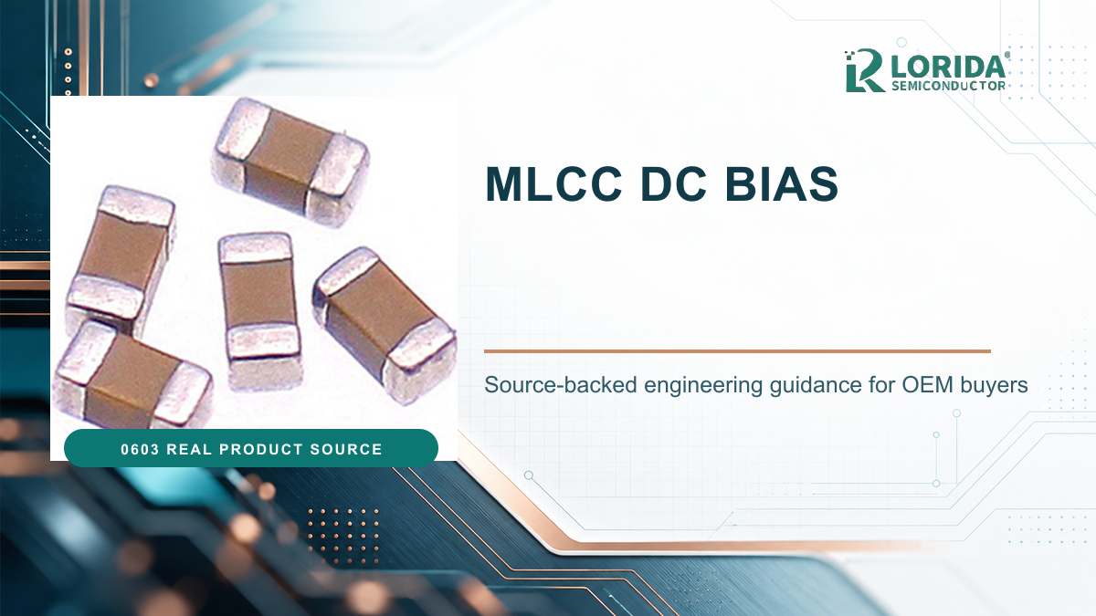
An MLCC must be selected by effective capacitance at the real operating voltage, not by the nominal value printed in the BOM. Class 2 ceramic dielectrics can lose capacitance when DC voltage is applied, so OEM approval must include the exact part number, its DC-bias curve, temperature range, measurement condition and circuit-level margin.
Key Takeaways
What buyers should verify before approving an MLCC
Do not treat rated voltage as proof that nominal capacitance remains available at that voltage.
Use the manufacturer curve or simulation model for the exact ordering code, package and dielectric.
Combine DC bias with tolerance, temperature, frequency and ageing instead of checking each factor in isolation.
Validate the circuit at minimum effective capacitance and the full operating condition.
Keep the curve, test setup and acceptance limit in the RFQ and sample-approval record.
What Is MLCC DC Bias?
Applied DC voltage changes the effective capacitance
DC bias is the change in capacitance that occurs while a DC voltage is applied across a multilayer ceramic capacitor. Murata states directly that MLCC capacitance changes when DC bias voltage is applied. The effect is especially important for high-dielectric-constant Class 2 materials used to obtain high capacitance in a small package. It is not the same as voltage rating: a component may remain below its rated voltage yet deliver less capacitance than the schematic assumes.
TDK therefore provides separate DC-bias models for MLCC simulation in addition to simple and precise equivalent-circuit models. That distinction is practical evidence that a nominal capacitance and a rated voltage alone are insufficient inputs for power-rail decoupling, converter stability, hold-up or filtering calculations.
Why Can Two Equal-Value MLCCs Behave Differently?
Package, dielectric and construction change the curve
Two capacitors marked with the same nominal capacitance and voltage can have different effective capacitance because the internal dielectric thickness, electrode geometry, case size and material formulation differ. The manufacturer curve must therefore match the full part number. A generic graph copied from another series cannot close an approval gate.
Temperature codes describe a different characteristic. TDK lists X7R as -55 to +125 °C with capacitance change within ±15% over that temperature range. That ±15% temperature band does not include DC-bias loss, initial tolerance, ageing or frequency dependence. TDK also lists an 0805-size low-profile example, CGB4B1X7R1A225M055AC, as 2.2 µF, 10 VDC, 2.00 × 1.25 × 0.50 mm, with ±20% capacitance tolerance. Its published characterization sheet shows capacitance falling as the applied voltage rises. Those figures apply only to that named TDK part, not to every X7R or any unspecified LORIDA item.
Six OEM Checks for Effective Capacitance
Turn a catalog value into a circuit-ready value
Lock the exact ordering code. Record manufacturer, series, case size, nominal capacitance, tolerance, rated voltage and dielectric. Do not approve a family-level description when the bias curve is part-specific.
Define the maximum steady DC voltage. Include rail tolerance, startup and operating state. A 5 V rail is not always exactly 5 V, and a converter output may overshoot.
Read the part-specific curve or model. Use capacitance change at the expected voltage, preferably across the complete operating range. TDK offers dedicated DC-bias SPICE models for many commercial and automotive MLCC series.
Add temperature and initial tolerance. X7R permits ±15% temperature-related change from -55 to +125 °C, while the part itself may also carry ±10% or ±20% initial tolerance. Do not simply subtract percentages without following the supplier method; use the published model or worst-case evidence.
Include frequency and ageing. Measurement frequency and AC amplitude affect reported capacitance, and Class 2 ceramics age logarithmically after manufacture or heat treatment. Ask the supplier to state the measurement condition and ageing reference.
Validate the circuit. Test control-loop stability, ripple, transient response, noise or hold-up using the minimum effective capacitance. Record the rail voltage, ambient temperature, load, board, instrument and pass limit.
| Approval input | Evidence required | Risk if omitted |
|---|---|---|
| Exact part number | Datasheet and ordering code | Wrong construction or curve |
| DC operating voltage | Rail maximum and transient review | Overstated available capacitance |
| Bias curve | Manufacturer graph, CSV or model | Unverified derating assumption |
| Temperature | Dielectric code and real ambient | Combined capacitance shortfall |
| Frequency and ageing | Test condition and reference time | Lab-to-field mismatch |
| Circuit validation | Minimum-capacitance test record | Instability, ripple or reset failure |
How Should an OEM Compare Candidate Parts?
Compare effective capacitance at the same condition
Normalize every candidate to the same DC voltage, temperature, frequency, AC test amplitude and ageing condition. Then compare effective capacitance, impedance, ESR, case size, flex-crack mitigation, termination, qualification and supply documentation. A larger case or higher voltage rating may improve effective capacitance, but that is not guaranteed without part-specific data.
Kyocera AVX explains that Class 2 bulk capacitance change under DC bias can be substantial, while its X7R product guidance says applied-voltage capacitance change must be acceptable for the application. Murata’s training material distinguishes temperature-compensating types, where voltage has negligible effect on capacitance, from high-dielectric-constant types, where voltage affects capacitance. That makes dielectric choice a functional design decision rather than only a sourcing preference.
What Should the RFQ and Sample Report Contain?
Request traceable electrical evidence
The RFQ should state the complete ordering code or approved envelope, nominal capacitance, minimum effective capacitance, maximum DC voltage, temperature range, measurement frequency and amplitude, case size, termination, qualification requirement, packing and annual demand. Ask the supplier to return the current datasheet, bias curve or simulation file and the lot-level sample data needed by your control plan.
For LORIDA sourcing, review the MLCC category, the ceramic capacitor category, and the engineering inquiry page. Submit the operating rail, package constraint and minimum effective capacitance so candidate parts can be compared under one defined condition.

Frequently Asked Questions
Does an MLCC keep its rated capacitance at rated voltage?
Not necessarily, especially for Class 2 high-capacitance dielectrics. Rated voltage defines an electrical limit under the supplier’s conditions; it does not guarantee that the nominal capacitance remains available when that voltage is applied. Use the DC-bias curve or model for the exact part number at the actual rail voltage. Then combine that result with tolerance, temperature, frequency and ageing before checking the circuit. If the supplier does not provide part-specific evidence, keep the effective capacitance unverified rather than substituting a generic graph.
Is X7R always better than X5R for DC bias?
No; the dielectric code alone does not rank DC-bias performance. X7R and X5R primarily define temperature range and permitted temperature-related capacitance change. Internal construction, case size, rated voltage and material formulation determine the part-specific bias curve. Compare exact ordering codes at the same voltage and temperature. X7R is commonly specified for -55 to +125 °C with ±15% temperature change, but that number must not be mistaken for the separate voltage-coefficient behavior. Ask for both the temperature characteristic and the bias curve so procurement cannot substitute one requirement for the other.
Can a higher voltage rating reduce MLCC capacitance loss?
It can improve margin in some part comparisons, but it is not a universal rule. A higher-voltage part may use a construction that retains more capacitance at a given rail, yet package size, dielectric thickness and manufacturer design also change. Select candidates using their published DC-bias curves, not the ratio of operating voltage to nameplate rating alone. Confirm that the proposed substitute also satisfies size, impedance, ESR, flex-crack, qualification and supply requirements. If two parts use different case sizes or dielectrics, compare their effective capacitance at the same electrical and thermal condition before deciding.
How should effective capacitance be verified in the finished circuit?
Verify the circuit function at the minimum effective capacitance and worst operating condition. For a power rail, measure ripple, transient response, startup, stability and reset margin at the maximum DC voltage, relevant temperatures and real load steps. Record the PCB revision, component lot, instrument, test point and pass limit. Direct capacitance measurement on an assembled board may be distorted by parallel paths, so use a controlled component measurement or manufacturer model alongside functional testing. Retain the waveform and calculation in the sample report so a later approved-source change can be evaluated against the same baseline.
Sources and Review Note
Primary manufacturer references
Last Updated: October 20, 2026. Technical review used the cited primary manufacturer sources. No individual author or reviewer name is displayed because a confirmed public byline identity was not available.