

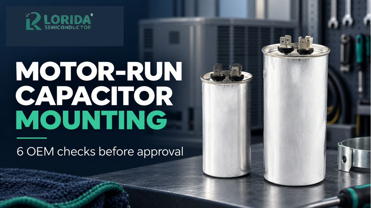
A motor-run capacitor should be approved only after the OEM confirms mounting position, fixing method, terminal style, clearance, ambient temperature, and the exact supplier drawing. Motor-run capacitors may support any-position mounting in one documented series, but that does not make every housing, bolt, clip, or terminal interchangeable. Use the exact series datasheet and a first-article fit check as the release gate.
Key Takeaways
Six checks before release
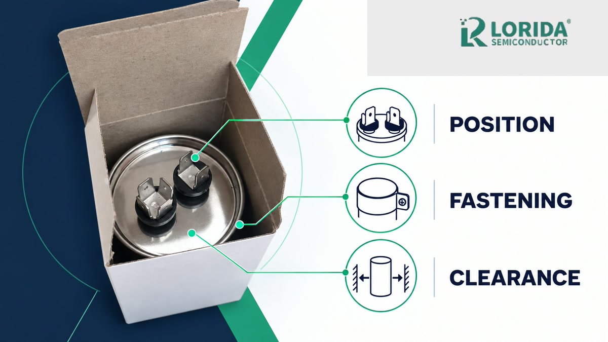
Confirm whether the exact series permits any-position mounting.
Match the fixing method and stud torque to the supplier drawing.
Verify terminal type, connector fit, and service access.
Protect overpressure features and required clearances.
Check ambient temperature, voltage, current, and harmonics together.
Approve production only after a documented first article.
What the mounting specification actually controls
Position is a series-level statement, not a universal rule
KEMET's C28 and C87 motor-run capacitor datasheets both state “Any position” for mounting. That statement belongs to those documented constructions and operating conditions. The C28 is a cylindrical plastic-case design; the C87 is an aluminum-case design with overpressure protection. An OEM should therefore record the exact series and construction before applying the mounting statement to a production drawing.
The same C87 document specifies a continuous service type, a -25°C to +85°C temperature range for the general family, 50–60 Hz rated frequency, and a maximum altitude of 2,000 m. These limits show why mechanical placement cannot be reviewed in isolation: enclosure temperature, airflow, elevation, and electrical stress remain part of the approval.
Fixing hardware must follow the documented option
TDK's B33331 CBB65A-1 datasheet identifies an optional bottom fixing stud and gives an M8 maximum torque of 5 Nm for the 50 mm diameter version. KEMET's C87 document gives 5 Nm for M8 and 10 Nm for M12 fixing bolts. These are manufacturer examples, not generic values. The purchasing drawing must identify the ordered fixing option, and the assembly instruction must repeat the supplier's current torque limit.
| Published example | Mounting statement | Relevant numeric detail | OEM action |
|---|---|---|---|
| KEMET C28 | Any position | -25°C to +85°C; 2,000 m | Verify enclosure temperature and altitude |
| KEMET C87 | Any position | M8 5 Nm; M12 10 Nm | Control bolt option and torque |
| TDK B33331 | Optional bottom stud | M8, 5 Nm max for 50 mm can | Use the exact ordered drawing |
How to validate the installation before production
Check the bracket, stud, clip, and terminal as one system
Start with the enclosure CAD and the supplier drawing. Confirm can diameter and height, stud or clip position, bracket contact area, terminal orientation, connector insertion path, wire bend radius, and tool access. The capacitor must not be used as a structural spacer, and the fixing method should restrain vibration without crushing or deforming the can. Record the washer, nut, bracket, and torque-control method in the assembly specification.
Terminal selection matters because motor-run families are offered with different connections. TDK lists 2+2 fast-on terminals measuring 6.3 × 0.8 mm for the B33331 example. KEMET's C27 system lists single or double faston options at the same 6.3 × 0.8 mm size as well as cable-terminal alternatives. Confirm the delivered terminal style, mating connector, current capacity, pull retention, and insulation clearance rather than treating all top decks as equivalent.
Preserve safety clearances and overpressure operation
KEMET's C87 data gives a minimum air distance of 5 mm between live parts and 6 mm between live parts and the case. The same series uses an overpressure-protection construction. Do not place a rigid obstruction where it could interfere with the documented safety mechanism, and do not route wires so tightly that service movement, vibration, or terminal replacement can damage insulation.
Electrical margins must remain consistent with the mechanical environment. Both KEMET C28 and C87 specify maximum permissible voltage of 1.10 times rated voltage and maximum permissible current of 1.30 times rated current for the cited series. These values are not a license to operate continuously at the limit; they are examples of why the exact datasheet, temperature profile, waveform, and expected service life belong in the RFQ and validation plan.
First-article approval and supplier communication
Use a physical release gate
Inspect the received part number, capacitance and voltage marking, case condition, terminal construction, fixing feature, and drawing revision. Fit the capacitor into the actual bracket or enclosure, apply the controlled fastening process, connect the production harness, and photograph the result. Confirm clearance to live metal, covers, heat sources, fans, and service tools. If the alternate supplier changes the deck, stud, diameter, or terminal geometry, repeat the fit review.
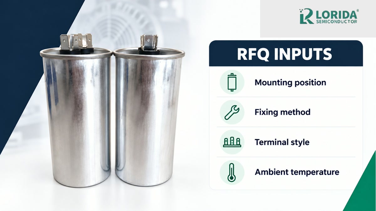
For sourcing, send the capacitor function, rated voltage and frequency, required capacitance and tolerance, mounting orientation, fixing method, terminal style, ambient range, altitude, waveform or harmonic content, enclosure drawing, and required approvals. Review LORIDA's motor capacitor range, compare related CBB65 terminal mapping guidance, or send the complete package through the engineering inquiry page.
Frequently Asked Questions
Can every CBB65 motor-run capacitor be mounted in any position?
No, any-position mounting must be confirmed for the exact series and construction. KEMET publishes “Any position” for its C28 and C87 examples, but those statements apply with their documented ratings, materials, and safety constructions. A visually similar CBB65 capacitor may use another fixing feature, deck, resin, or pressure-protection design. Put the exact part number and current supplier drawing in the release package and verify the installed first article.
What torque should be used on a bottom mounting stud?
Use only the torque stated for the exact stud and capacitor series. TDK's B33331 example specifies a maximum of 5 Nm for an M8 stud on the 50 mm can, while KEMET's C87 example lists 5 Nm for M8 and 10 Nm for M12. These figures demonstrate that stud size and construction matter; they are not universal assembly values. Record the controlled tool, washer stack, bracket material, and current drawing revision.
Are fast-on terminals interchangeable across motor-run capacitors?
No, confirm blade size, number, layout, material, and mating connector. The cited TDK example uses 2+2 fast-on terminals at 6.3 × 0.8 mm, while supplier families may also offer single faston, double faston, or cable exits. Even when blade dimensions match, top-deck geometry and wire routing can differ. Validate connector engagement, retention, insulation clearance, and service access on the delivered part.
What information should an OEM include in a motor-run capacitor RFQ?
Include the electrical duty and the complete mechanical installation. State capacitance, tolerance, rated voltage, frequency, waveform or harmonic content, ambient range, altitude, service-life target, approvals, mounting orientation, fixing method, terminal style, connector, enclosure drawing, airflow, and nearby heat sources. Attach photographs or a CAD section of the bracket and cover. This lets the supplier confirm both performance and fit before a production sample is approved.
Need a motor-run capacitor mounting review?
Send the enclosure drawing, fixing method, and duty conditions
LORIDA can help organize the electrical and mechanical inputs for supplier confirmation and first-article validation.
Sources
Manufacturer documents used for the numeric examples
Last Updated: October 1, 2026. Published values are examples for the cited series; confirm the current drawing and datasheet for the exact ordered part.


