MOV varistor aging is controlled by cumulative surge stress, temporary overvoltage, temperature, and the exact protection circuit—not by disc diameter alone. Repeated pulses can shift electrical behavior even when the coating looks intact, while sustained overvoltage can create dangerous heating. OEM buyers should therefore qualify the complete part number against the real waveform, pulse count, ambient temperature, layout, fuse or thermal disconnect, and end-of-life limits. The six checks below turn a vague “same voltage MOV” request into an auditable RFQ.

Why MOV aging must be treated as a system question
Single-pulse ratings do not describe repetitive duty
TDK states that maximum surge capability depends on pulse amplitude, duration, and the number of pulses over the device lifetime. Its general technical information defines the familiar maximum non-repetitive surge current with an 8/20 µs waveform: an 8 µs rise time and a 20 µs decay to half value. If the pulse is longer or repeated, the allowable current must be derated using the manufacturer’s curves. A catalog peak-current number is therefore not a reusable energy budget. Procurement must retain the waveform, count, interval, source impedance, and the exact datasheet revision used for selection.
Degradation can be electrically important before it is visible
Bourns explains that cumulative degradation can occur as more surges or voltage swells arrive. The MOV may still look functional while no longer providing the intended protection, and severe overstress can progress toward a conductive failure path. Visual inspection is useful for cracks, discoloration, coating damage, and lead defects, but it cannot replace electrical measurement. A qualification plan should define the allowed change in varistor voltage, leakage current, and clamping behavior after the specified stress sequence.
Six OEM checks for aging and replacement decisions
1. Lock continuous AC/DC voltage and temporary overvoltage
Start with the highest continuous RMS or DC voltage at the MOV location, including mains tolerance, generator regulation, and normal operating variation. Then list temporary overvoltage events separately: lost neutral, line faults, load dump, startup overshoot, and abnormal control states. Bourns warns that an MOV is intended to conduct high power for very short durations—typically on the order of 8 to 20 microseconds—not sustained energy. Continuous rating and transient rating solve different problems, so both must appear in the RFQ.
2. Define the complete surge waveform and pulse count
Specify open-circuit voltage, short-circuit current, source impedance, waveform, polarity, pulse count, interval, and temperature. IEC 61000-4-5 combination-wave testing commonly uses a 1.2/50 µs open-circuit voltage and an 8/20 µs short-circuit current, as summarized in current TDK technical material. These numbers describe the generator, not a universal component rating. If field events differ, convert them only with an approved engineering method and confirm the selected part on the real circuit.
3. Compare varistor voltage and clamping voltage at stated current
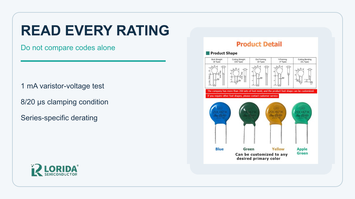
Varistor voltage is meaningful only with its test current and tolerance. Many radial MOV datasheets specify nominal varistor voltage at 1 mA DC and clamping voltage with an 8/20 µs current at a stated peak current. Littelfuse UltraMOV data, for example, separates the 1 mA DC varistor-voltage test from the 8/20 µs clamping-voltage condition. Do not compare two voltage columns without their currents and waveforms. Record minimum, nominal, and maximum values and the test temperature.
4. Apply temperature and repetition derating
Use the product-series derating graph rather than a generic percentage. Littelfuse notes that transient energy delivered in rapid succession creates average power equal to energy per pulse multiplied by pulse frequency, and that this power must remain within the series limits. Its UltraMOV documentation also shows temperature derating above the rated ambient boundary. Heat from nearby resistors, relays, semiconductors, and enclosed power supplies must be included because elevated temperature can reduce surge margin and accelerate failure mechanisms.
5. Control layout, leads, protection, and mounting
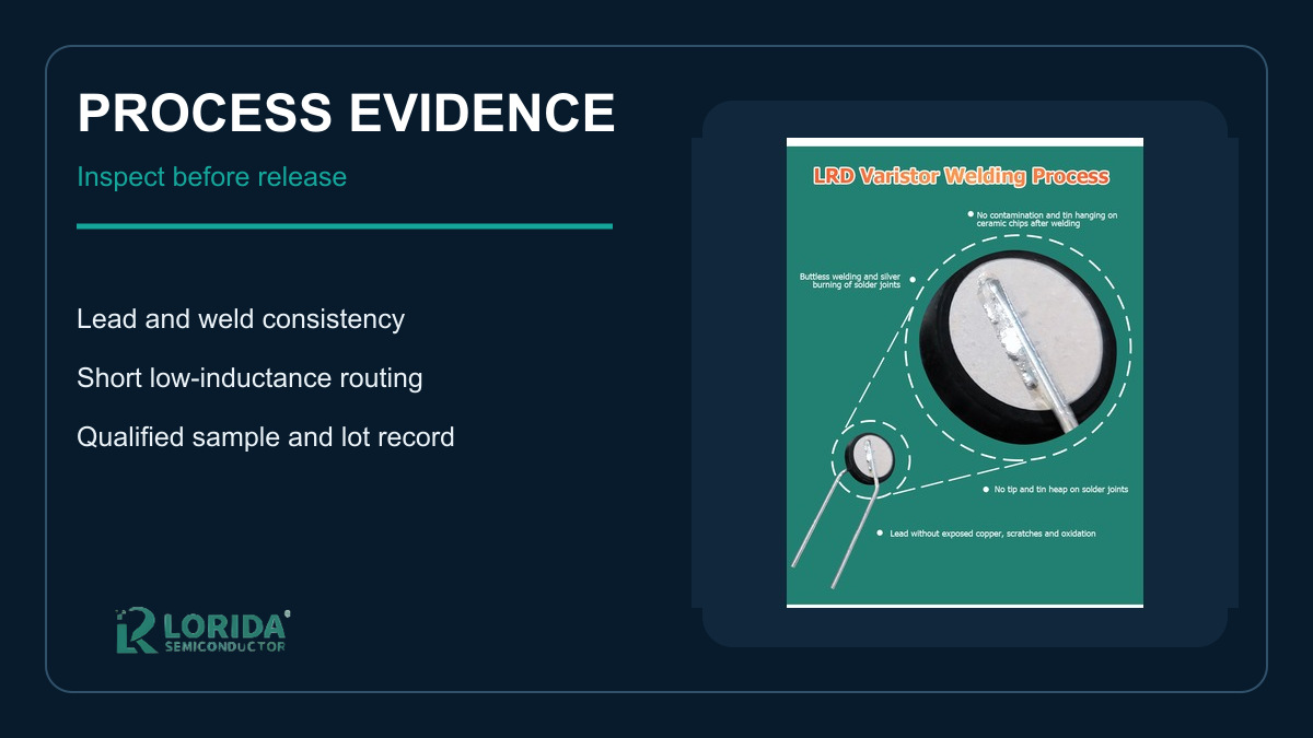
Place the MOV close to the protected node with short, closely routed conductors. Littelfuse explains that voltage drop in the connection reduces protection effectiveness, while lead inductance increases the voltage seen during fast current rise. Review creepage, clearance, lead forming, coating clearance, solder temperature, board support, and proximity to heat-sensitive materials. For mains applications, coordinate the MOV with a fuse, thermal cutoff, or thermally protected MOV according to the product standard and fault analysis; the MOV must not be treated as the disconnect device.
6. Qualify samples and define an end-of-life screen
Before release, measure initial varistor voltage, leakage current, and clamping performance using safe approved equipment. Apply the agreed surge sequence, allow thermal recovery, then repeat the measurements and inspect the body, coating, leads, and solder joints. The acceptance criteria must come from the exact manufacturer datasheet or project specification. Retain sample identity, lot, measurement method, instrument status, photos, and deviation approvals. For sourcing support, buyers can review LORIDA’s varistor range and send the real surge duty with the RFQ.
RFQ evidence that separates selection from guesswork
A compact qualification table
| Decision | Required input | Release evidence |
|---|---|---|
| Continuous duty | Maximum RMS/DC voltage, tolerance, frequency, TOV | Approved voltage margin and fault review |
| Surge duty | Waveform, source impedance, peak, count, interval | Series-specific pulse-derating check |
| Protection level | Varistor voltage and clamping current | Maximum protected-node voltage |
| Thermal duty | Local ambient, repetition rate, nearby heat | Measured temperature and derating record |
| Mechanical design | Disc size, lead form, spacing, coating | Drawing and approved assembly photos |
| End of life | Electrical change limits and fault protection | Post-stress data and disconnect verification |
Example of a safe comparison method
Suppose two parts both carry a 471 marking. That code alone does not prove equivalence. The buyer must compare continuous RMS and DC ratings, the 1 mA varistor-voltage tolerance, clamping voltage at the stated 8/20 µs current, single-pulse energy, peak current, repetitive-pulse curves, operating temperature, disc size, lead spacing, safety recognition, and change criteria after stress. The correct conclusion is “candidate pending waveform and sample validation,” not “same marking means same protection.”
Key Takeaways
Six records to keep with the approved part
Highest continuous voltage and every credible temporary overvoltage.
Surge waveform, source impedance, pulse count, interval, and temperature.
Varistor and clamping voltages with their exact test currents.
Series-specific temperature and repetitive-pulse derating.
Layout, lead form, fuse or thermal-disconnect coordination.
Initial and post-stress electrical measurements for the approved lot.
Frequently Asked Questions
Does an MOV wear out after one surge?
Not necessarily; the outcome depends on surge amplitude, duration, waveform, temperature, and the part’s rated capability. A pulse within the manufacturer’s limits may cause little measurable change, while a larger, longer, hotter, or repeated stress can produce cumulative degradation. Do not infer condition from appearance alone. Compare pre- and post-stress varistor voltage and leakage current, and follow the exact series criteria. If the field surge is unknown, capture or bound it before deciding whether reuse is acceptable.
Can I replace an MOV using only the printed voltage code?
No; a printed voltage code is only one part of the electrical and mechanical definition. Two devices with the same nominal code can differ in tolerance, continuous AC/DC voltage, clamping voltage, surge current, energy rating, disc size, lead spacing, coating, safety approvals, temperature range, and repetitive-pulse capability. Request the full order code and controlled datasheet, then verify the actual waveform and protected-node limit. Approve the alternate only after circuit and sample validation.
Why are 8/20 µs and 1.2/50 µs both mentioned?
They describe different parts of a standard surge-generator condition. In IEC 61000-4-5 combination-wave testing, 1.2/50 µs describes the open-circuit voltage wave, while 8/20 µs describes the short-circuit current wave. The installed MOV sees a voltage-current interaction determined by the generator, wiring, source impedance, and load. Always state the waveform beside every peak value; a peak current without its time shape is incomplete engineering evidence.
Should a fuse be placed in series with the MOV?
The protection circuit needs an approved disconnect strategy, but the correct device and placement depend on the application and safety standard. An upstream fuse may clear some faults, while a thermally protected MOV or closely coupled thermal cutoff can respond to local heating. Coordination requires available fault current, fuse time-current behavior, temporary overvoltage, enclosure materials, and the MOV failure analysis. Do not add a generic fuse value from an example; have the responsible engineer validate the complete circuit.
Last Updated: October 13, 2026. Technical review: LORIDA engineering content team. Sources: TDK SIOV Metal Oxide Varistors General Technical Information; TDK overvoltage-protection technical articles; Littelfuse Metal-Oxide Varistors and UltraMOV datasheets; Bourns “Tips on Selecting the Right MOV Surge Suppressor.” Manufacturer documents govern. For an application review, contact LORIDA with voltage, waveform, pulse count, temperature, layout, and required approvals.