Adjust a trimmer potentiometer only after confirming the pinout, safe power state, target setpoint, permitted adjustment method and final verification plan. A screwdriver turn is not a complete calibration procedure: the OEM must control the circuit condition, mechanical stop, measurement setup and recorded acceptance limit.

Key Takeaways
What an OEM adjustment instruction must control
Confirm which terminal is the wiper and which two terminals form the resistive element before applying power.
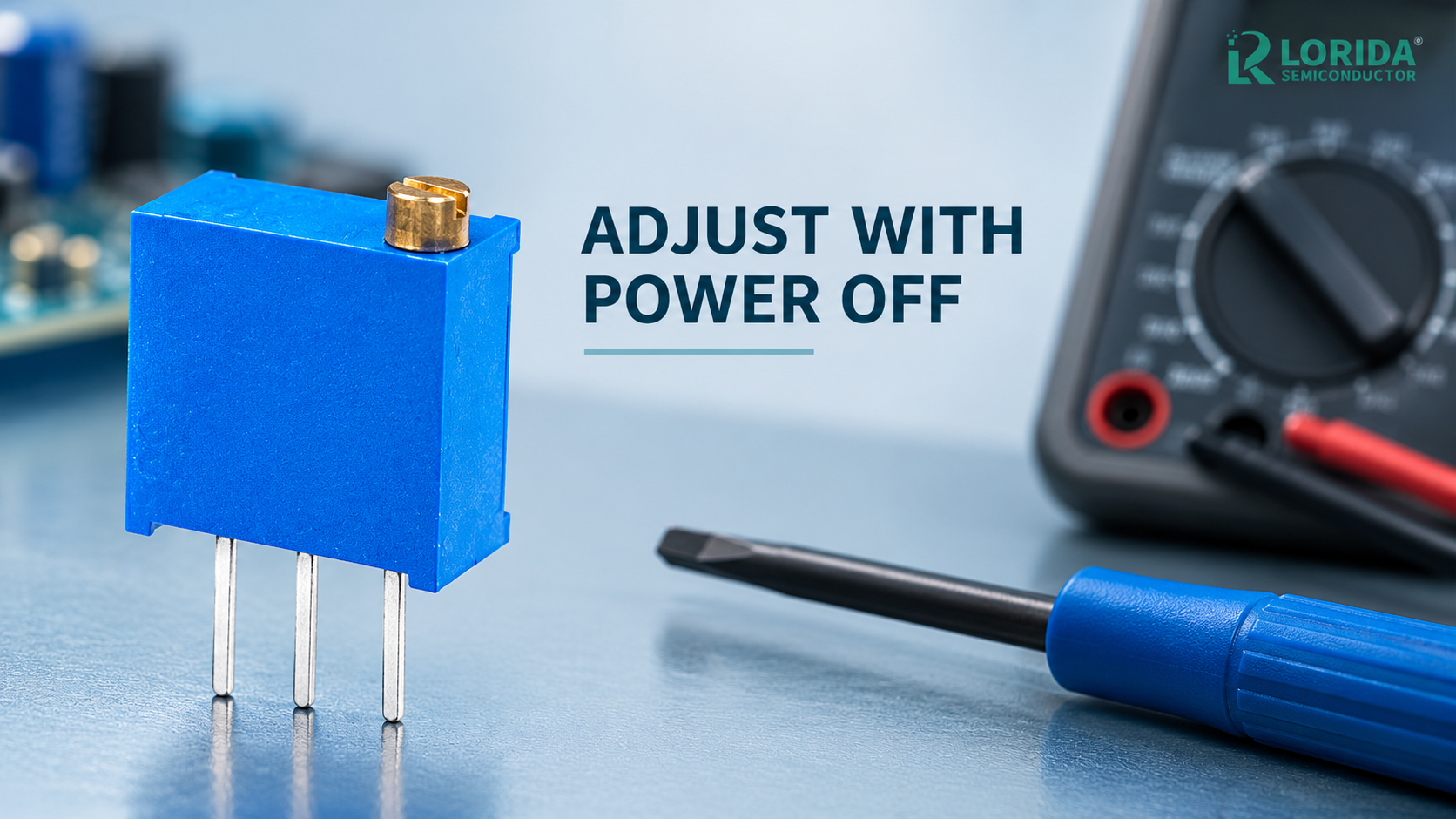
Use power-off adjustment unless the circuit owner has documented a safe energized calibration method.
Never use the mechanical end stop as a torque reference; approach the target gradually.
Measure the functional circuit output as well as resistance when the trimmer is installed.
Lock the acceptance range, environmental condition, tool and readback method in the work instruction.
How Does a Trimmer Potentiometer Work?
The wiper divides a resistive element
A three-terminal trimmer potentiometer has two end terminals connected to a resistive element and a wiper terminal that moves along that element. Used as a voltage divider, the output is taken from the wiper and one end terminal. Used as a rheostat, the circuit uses the wiper with one end terminal. The direction in which resistance or output changes depends on the chosen terminals and the mechanical orientation, so an assembly drawing should identify pins rather than say only “turn clockwise.”
Published series data shows why the exact part matters. Bourns lists its 3362 single-turn family from 10 Ω to 2 MΩ, with a 240° nominal mechanical angle. Vishay lists the sealed T7 family from 10 Ω to 2.2 MΩ. Piher’s PT-10 datasheet publishes a 235° ± 5° mechanical angle and a 220° ± 20° electrical angle. These are manufacturer-specific examples, not universal LORIDA ratings.
Why Should the Power State Be Defined First?
Power-off prevents uncontrolled circuit movement
Power-off adjustment is the safer default because a slipping tool, wrong terminal assumption or fast turn cannot immediately drive the circuit into an overvoltage, overcurrent or unstable condition. Discharge stored energy, verify the node is safe and use an insulated tool when nearby conductors could remain energized. If live calibration is genuinely required, the equipment owner should specify current limiting, personal protection, probe points, permissible adjustment range and the fault response before work begins.
Do not infer electrical safety from the small size of the trimmer. Bourns publishes 500 VDC insulation resistance testing with a 1,000 MΩ minimum for the 3362 family and a 900 VAC sea-level dielectric-withstanding value, but those numbers describe a named component under stated conditions. They do not prove that an assembled product is safe to touch or adjust while energized.
Six OEM Checks Before Turning the Adjuster
Convert calibration into a repeatable process
Verify the exact part and pinout. Record manufacturer, series, resistance code, tolerance, terminal drawing and adjustment direction. Check whether the part is single-turn or multiturn and whether top or side adjustment is intended.
Define the safe circuit state. State whether power must be off, which capacitors must be discharged and how zero energy is confirmed. For an energized procedure, define current limits, isolation, guarded probe points and stop conditions.
Specify the adjustment tool. Use a blade size that fits the slot and an insulated non-damaging tool when appropriate. An oversized blade can crack the rotor; an undersized blade can slip and damage nearby components.
Set a measurable target. Give the test point, instrument, range, resolution, stabilization time and allowable tolerance. “Tune until correct” is not auditable. Record ambient temperature and supply condition when they affect the result.
Respect mechanical limits. Turn slowly and stop when the reading reaches the target. Do not continue against the end stop. Piher publishes a PT-10 rotational torque range of 0.4 to 2 N·cm and a stop torque above 5 N·cm; those values illustrate the distinction between normal movement and the stop, but they apply only to that series.
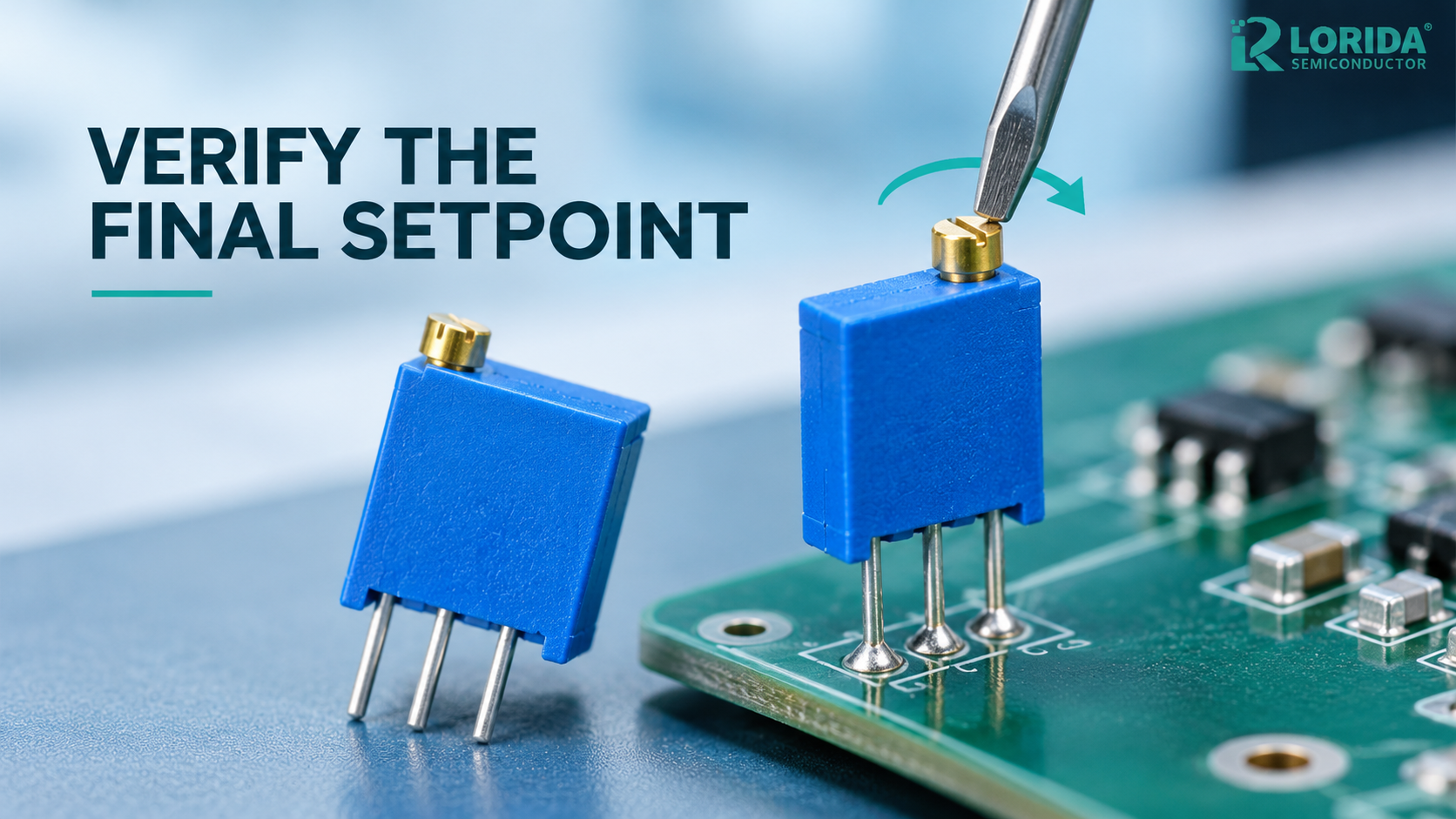
Verify and document the final state. Recheck the result after removing the tool, cycling power if required and allowing the circuit to stabilize. Record the measured output, acceptance decision and any sealing or tamper-control step.
| Control point | Required evidence | Common failure | OEM response |
|---|---|---|---|
| Identity | Exact part number and drawing | Wrong pin or orientation | Photo and terminal map |
| Energy state | Power-off or approved live method | Unsafe node movement | Discharge and limit procedure |
| Tool | Blade type and insulation | Slip or rotor damage | Tool part number |
| Target | Test point and tolerance | Subjective adjustment | Recorded measurement |
| Mechanical travel | Series-specific angle and torque | End-stop overload | Slow approach; no forced turn |
| Final release | Readback after stabilization | Drift or tool-loading error | Power-cycle and remeasure |
Which Datasheet Numbers Matter for Adjustment?
Electrical and mechanical limits are linked
Resistance range is only the first field. Bourns specifies a ±10% total resistance tolerance for the 3362 family and adjustability of ±0.05% in divider mode and ±0.15% in rheostat mode. The same family is rated 0.5 W at 70 °C, derated to zero at 125 °C, with an operating range of -55 °C to +125 °C. These figures help an engineer separate nominal resistance, adjustment resolution and thermal loading.
Vishay publishes 0.5 W at 70 °C for the T7 family, while Piher publishes 0.15 W at 50 °C for PT-10 and 0.33 W at 70 °C for PTC-10. Piher also distinguishes endurance: up to 100,000 cycles for PT-10 and 10,000 cycles for PTC-10 under its stated conditions. These differences show why purchasing must not substitute a visually similar trimmer without repeating the electrical, mechanical and life review.
How Should the Final Setpoint Be Verified?
Measure function, not only loose-part resistance
When the trimmer is part of a feedback, bias, threshold or gain network, the functional output is normally the acceptance variable. Connect the specified instrument to the defined test point, use the stated supply and load, and allow the circuit to reach the required thermal or electrical stability. Remove the adjustment tool before final readback so tool pressure does not mask a marginal setting.
If resistance must be measured directly, isolate the component from parallel circuit paths or use an approved in-circuit method. Record which terminals were measured and whether the value was taken before or after soldering. A final procedure may include a power cycle, warm-up, vibration screen or environmental check when the product risk requires it. Any adhesive or seal must be compatible with the component and must not enter the adjustment mechanism.
What Should Be Included in the RFQ and Work Instruction?
Use part-specific, auditable fields
Ask the supplier to return the full ordering code, resistance, tolerance, power condition, temperature range, temperature coefficient, adjustment angle, torque, stop strength, endurance, terminal layout, sealing level, recommended tool and applicable qualification standard. Label every value as guaranteed, typical or test-derived. For the factory instruction, add the PCB reference designator, assembly orientation, safe power state, test point, instrument, target, tolerance, stabilization time, operator action and final record field.
For related sourcing, review the LORIDA variable resistor category, the 3006P trimming potentiometer page, and the variable components overview. Send the circuit role, resistance, adjustment access and production test conditions for a model-specific comparison.
Frequently Asked Questions
Can a trimmer potentiometer be adjusted while powered?
Only when the equipment owner has approved a live-calibration method and the circuit can remain within safe limits. The instruction should define current limiting, isolation, guarded probe points, insulated tools, personal protection, the permitted adjustment range and an immediate stop condition. Power-off adjustment is the safer default because a wrong turn or slipped tool cannot instantly drive the powered circuit. Even when live adjustment is allowed, verify the final value after removing the tool and, where required, after a power cycle and stabilization period.
Which trimmer potentiometer terminal is the wiper?
The wiper is the moving terminal identified by the exact manufacturer drawing; do not rely only on physical position. Many three-terminal layouts place the wiper at terminal 2, but orientation, packaging and PCB viewing side can create mistakes. Match the supplier drawing to the board reference designator, then confirm with a resistance measurement while the part is isolated and unpowered. The two end terminals should show approximately the total resistance, while resistance from the wiper to either end changes with adjustment.
How far should a single-turn trimmer be rotated?
Rotate only far enough to reach the documented electrical target, and never force the adjuster against the mechanical stop. Single-turn families often provide roughly one partial revolution; for example, Bourns publishes 240° nominal for 3362 and Piher publishes 235° ± 5° for PT-10. Those values are series-specific, so the work instruction should cite the actual part. Approach the setpoint slowly, use the correct blade, remove the tool and verify the reading after stabilization. If the target cannot be reached within normal travel, stop and investigate the circuit or selected resistance value instead of applying more torque.
Should the trimmer be measured in ohms or by circuit output?
Use the circuit output when that is the functional requirement, and use resistance only when the method isolates parallel paths and identifies the terminals. A loose resistance value may not prove that a feedback threshold, bias voltage or gain is correct under the real supply, load and temperature. Define the test point, instrument, tolerance and stabilization time. For production control, record the final functional result and any direct resistance check required for traceability, then repeat after a power cycle if the product specification calls for it.
Sources and Review Note
Primary manufacturer references
Last Updated: October 17, 2026. Technical review used the cited primary manufacturer sources. No individual author or reviewer name is displayed because a confirmed public byline identity was not available.