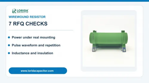
Select a wirewound resistor by resistance, continuous dissipation, pulse energy, peak voltage, inductance, thermal path and mechanical construction—not by wattage alone. The RFQ should include the real current or voltage waveform, repetition rate, ambient and mounting conditions, allowable resistance drift and required safety behavior. These inputs let a supplier compare an exact series and order code rather than substitute a visually similar part.
Rated power is tied to stated ambient and mounting conditions.
Pulse energy, peak power and repetition must be checked together.
Conventional winding can add inductance; non-inductive construction must be requested when required.
Voltage, insulation, coating, terminals and failure behavior belong in the RFQ.
1. Define the resistance function and accuracy budget
Separate nominal value from tolerance, TCR and drift
Start with the circuit function: current limiting, discharge, precharge, damping, sensing or load simulation. State nominal resistance and the acceptable minimum and maximum after initial tolerance, temperature change and service drift. A purchasing tolerance describes the value at specified measurement conditions; it does not cover every change in operation. Temperature coefficient of resistance describes reversible change with temperature, while load-life and environmental tests describe longer-term stability.
As an external example, Ohmite lists its 50 Series at 0.1 Ω to 10 kΩ for the 3 W 53J size and 0.1 Ω to 20 kΩ for the 5 W 55J size. The same page lists TCR bands of ±90 ppm/°C below 1 Ω, ±50 ppm/°C from 1 Ω to 99 Ω and ±30 ppm/°C from 100 Ω upward. These figures belong only to that Ohmite series. They show why resistance value and temperature range must accompany a cross-reference request.
2. Calculate continuous power under real thermal conditions
Use electrical loss and the datasheet derating curve
For steady operation, calculate resistor power with P=I²R or P=V²/R at the worst credible combination of voltage, current and resistance tolerance. Then compare that result with the exact series rating at the actual ambient temperature. Include enclosure temperature, airflow, spacing from other hot parts and whether leads, a PCB, clips or a chassis carry heat away. A catalog wattage measured at 25 °C or 70 °C is not a guarantee at a higher local temperature.
Ohmite’s RW high-power SMD page illustrates the importance of test conditions: the RW5S0 is listed at 7 W at 25 °C but 5 W at 70 °C. Vishay’s WSC/WSN datasheet lists different operating-temperature endpoints across sizes, including +175 °C and +275 °C examples. Those values cannot be transferred to another construction. Ask for the proposed part’s power rating, reference temperature and derating curve, then verify the hotspot on the final assembly.
3. Describe pulse duty as a waveform
Peak watts do not describe deposited energy
Provide pulse amplitude, duration, shape, source impedance, repetition period and total number of events. A capacitor discharge, motor-braking event and repetitive switching pulse can produce the same apparent peak power but different energy and temperature rise. For a rectangular pulse, energy is power multiplied by time. For a changing waveform, integrate instantaneous power or provide an oscilloscope capture and numerical data so the supplier can compare it with the appropriate pulse curve.
Do not use a short-time-overload test as a general repetitive-pulse rating. Vishay’s CW datasheet includes a short-time overload test of five times rated power for sizes rated 3.75 W and smaller, or ten times rated power for 4 W and larger, for five seconds. It separately states a load-life test of 2,000 hours at rated power and +25 °C with a 1.5-hour on and 0.5-hour off cycle. These are defined tests for that family, not interchangeable design permissions.
4. Check voltage, insulation and fault behavior
Power calculations do not replace voltage limits
A high-resistance part may reach its limiting element voltage before reaching nominal wattage. State the maximum continuous voltage, transient peak, waveform polarity and whether the resistor is floating or referenced to chassis. Include required creepage, clearance, dielectric-withstand and insulation-resistance evidence. Vishay’s WSC/WSN datasheet provides one external example of dielectric withstand greater than 500 VAC and insulation resistance greater than 10⁹ Ω. Treat those as series-specific values.
Also define the expected response to overload. A resistor used for inrush limiting or discharge may need predictable open-circuit behavior, flame resistance or a separately coordinated fuse. Do not infer a safety approval from appearance, coating color or a standard printed on another part. Request the exact certification or qualification record for the proposed order code and evaluate it within the complete protection circuit.
5. Decide whether inductance matters
Specify non-inductive winding when the circuit needs it
Conventional wirewound resistors behave as both resistance and inductance because current flows through a coil. That inductance may be unimportant in a DC bleeder but significant in snubbers, fast switching, high-frequency loads or current-shunt paths. Describe rise time, switching frequency and allowable overshoot. If a non-inductive style is required, name that requirement explicitly and ask how resistance range or pulse capability changes.
Vishay states that its WSN variants use Ayrton-Perry winding and have a maximum resistance equal to one-half of the corresponding WSC range. This is a useful example of a real tradeoff: reducing inductance can change the available resistance range. Do not replace a conventional wirewound part with a “non-inductive” alternative until the supplier confirms resistance, pulse curve, temperature performance, dimensions and order-code evidence.
6. Match mechanical construction and thermal path
Body style, terminals and mounting affect performance
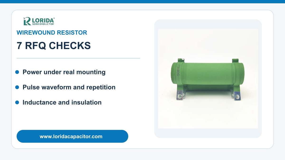
Wirewound resistors appear as axial ceramic bodies, cement blocks, aluminum-housed chassis parts and surface-mount packages. Specify body dimensions, lead diameter and spacing, terminal type, mounting hardware, vibration, coating, maximum height and nearby materials. A chassis-mounted part may require a defined surface finish, flatness, torque and interface material. An axial part needs adequate lead length and PCB spacing so the board does not become the unintended thermal bottleneck.
Review the LORIDA wirewound resistor category to align the requested construction with available product types. For broader alternatives, compare the cement resistor category and aluminum housed resistor category. Category appearance is only a starting point; approval should use a specific datasheet, drawing and sample.
7. Compare candidates and validate samples
Normalize the RFQ before making a substitution
| RFQ field | Provide | Controls |
|---|---|---|
| Resistance | Nominal value, tolerance, TCR, drift budget | Circuit accuracy over temperature and life |
| Continuous duty | Current, voltage, ambient, enclosure and mounting | Steady temperature and derating |
| Pulse duty | Waveform, duration, peak, period and event count | Energy, peak stress and cooling |
| Voltage and insulation | Continuous maximum, transient peak, isolation needs | Element and dielectric limits |
| Frequency behavior | Rise time, switching frequency, inductance limit | Conventional or non-inductive winding |
| Mechanical | Drawing, terminals, mounting, vibration and coating | Fit, heat flow and assembly |
| Evidence | Datasheet, pulse curve, qualification and samples | Traceable approval |
Test samples at minimum and maximum supply, highest ambient and the most demanding repetition rate. Measure the actual current or voltage waveform, resistor temperature and resistance before and after the defined test sequence. Inspect coating, terminals, solder joints and mounting surfaces. If the circuit relies on the resistor during a fault, include the protection device and abnormal sequence in the validation plan.
Record the approved manufacturer, complete order code, drawing revision and supporting curve. Purchasing should not accept a visually similar substitute without rerunning the comparison. Send the original part number, photos, waveform and environment through the LORIDA contact page for a datasheet-based sample review.
Frequently Asked Questions
Can I replace a wirewound resistor using only resistance and wattage?
No, resistance and wattage do not define pulse, voltage, inductance, temperature or mechanical behavior. Provide the original order code and datasheet plus continuous current and voltage, pulse waveform, repetition, ambient, mounting, body dimensions and terminal details. Confirm limiting voltage, insulation and required failure behavior. Two parts marked with the same ohms and watts may use different winding, coating and thermal assumptions. Validate the proposed sample in the final enclosure and retain temperature, waveform and post-test resistance evidence before approving a purchasing substitution.
Does a wirewound resistor always have too much inductance for switching circuits?
No, but conventional winding adds inductance and must be evaluated against the circuit’s rise time and frequency. Non-inductive techniques such as Ayrton-Perry winding can reduce inductance, although they may change resistance range or other ratings. State switching frequency, edge rate, allowable overshoot and physical loop layout in the RFQ. Ask for the exact construction and impedance or inductance evidence when it matters. Confirm behavior with the complete circuit because resistor winding and PCB interconnect both contribute to the transient response.
How should I specify repetitive pulses?
Specify the full waveform, duration, peak, repetition period, event count and cooling conditions. Add source impedance and the minimum and maximum resistance that the circuit can produce. Do not quote only peak watts or joules. A single-pulse curve may not allow an endless pulse train, and average power alone may hide a damaging short peak. Ask the supplier to identify the exact datasheet pulse curve and resistance-value limit used. Validate the hottest credible repetition on the final assembly and measure resistance change afterward.
What should a wirewound resistor RFQ contain?
A complete RFQ contains electrical duty, thermal conditions, construction, environment and evidence requirements. Include nominal resistance, tolerance, TCR, continuous current and voltage, maximum transient, pulse waveform, frequency or rise time, ambient and enclosure temperatures, airflow, mounting surface, body and terminal drawing, vibration, coating and required safety behavior. Attach the original part number for replacement work. Ask for a traceable datasheet, derating and pulse curves, qualification status for the exact order code, samples and an agreed validation plan.
Sources: Vishay WSC/WSN datasheet, Document 30102, revision March 25, 2025; Vishay CW datasheet, Document 30215; Ohmite 50 Series and RW Series official product pages.
Prepare a wirewound resistor RFQ
Send the waveform, thermal conditions, mechanical envelope and required evidence for a datasheet-based sample review.
Send your wirewound resistor requirementsLast Updated: September 14, 2026