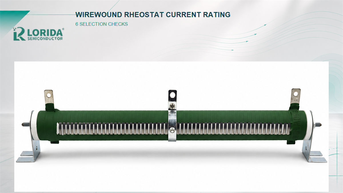
A wirewound rheostat current rating cannot be selected from watts alone. Calculate current at the lowest resistance the circuit can reach, check power in the active winding section, apply the maker’s ambient-temperature derating, and confirm the separate voltage, sliding-contact, terminal, ventilation, and duty limits. The six checks below convert a nominal power label into a traceable RFQ and sample-test plan for a tubular adjustable rheostat.
Key Takeaways
What the selection calculation must establish
Use the lowest effective resistance, not only the full winding resistance, when calculating worst-case current.
Check both equations: P = I²R and P = V²/R.
Treat power rating, maximum voltage, and sliding-contact current as separate limits.
Apply the manufacturer’s derating curve at the actual enclosure ambient and mounting condition.
Define whether adjustment occurs energized, how often it moves, and whether the duty is continuous, intermittent, or pulse.
Validate the final sample with current, voltage, temperature rise, contact stability, and post-test resistance evidence.
Why Watts Alone Do Not Define Rheostat Current
Current changes as the active resistance changes
A rheostat uses a fixed terminal and a movable contact to place only part of the winding in the circuit. When the contact moves toward the fixed terminal, the effective resistance falls. For a voltage-driven load, current rises as resistance falls. The full-body wattage printed on a product therefore does not prove that every contact position is safe. The designer must calculate the electrical stress at the minimum permitted setting and confirm how the manufacturer rates a partially used winding.
P = I²R → I = √(P/R)
P = V²/R → V = √(PR)
Use the applicable derated power and the actual active resistance. Then compare the result with the maker’s voltage and contact-current limits.
Power and voltage limits can produce different answers
Ohmite’s official rheostat page explicitly notes that voltage rating depends on resistance value. Its published Model P example is rated 225 W with a 1 Ω to 30 kΩ range and a 1300 V RMS maximum, while Model R is 500 W with a 1 Ω to 20 kΩ range and a 1450 V RMS maximum. These examples show that a higher power number does not replace a separate voltage check. The safe operating point is the most restrictive applicable limit, not the most favorable calculation.
Six Selection Checks
Checks 1–3: circuit, active resistance, and thermal duty
Checks 4–6: voltage, moving contact, and installation
The moving contact is not merely a mechanical accessory. It carries current through a limited contact area while crossing turns of resistance wire. Bourns’ potentiometer handbook warns that rheostat-mode current must stay within the particular unit’s maximum allowable wiper current and notes that 100 mA is a common maximum for many wirewound and cermet potentiometers. That statement concerns potentiometers and must not be transferred to an industrial tubular rheostat; it demonstrates why the contact limit needs its own manufacturer evidence.
Manufacturer Examples That Keep the Limits Separate
Use examples to build the RFQ, not to infer LORIDA specifications
| Official example | Published data point | Selection lesson |
|---|---|---|
| Vishay RT12 | 12 W at 25°C; 1 Ω to 2.2 kΩ; 300 V limiting element voltage | Power, resistance range, ambient reference, and voltage limit are separate fields. |
| Vishay RT12 | 1000 V RMS dielectric strength; 290° mechanical travel with tolerance | Insulation test and mechanical adjustment range do not come from the wattage. |
| Vishay rheostat range | RT25: 25 W; RT55: 55 W, both specified at 25°C | Compare like-for-like ratings at the same reference temperature. |
| Ohmite Model P | 225 W; 1 Ω to 30 kΩ; 1300 V RMS maximum; 310° rotation | Resistance, voltage, power, and travel must all match the application. |
| Ohmite Model R | 500 W; 1 Ω to 20 kΩ; 1450 V RMS maximum; 325° rotation | A larger power class still has a defined voltage and mechanical envelope. |
Worked Calculation for an RFQ Boundary
Calculate a screening point before asking for a sample
Assume an application requires 2.0 A through a minimum active resistance of 20 Ω. The winding section dissipates P = I²R = 2.0² × 20 = 80 W. The voltage across that active section is V = IR = 40 V. These are circuit requirements, not a product approval. The RFQ must still confirm whether the maker allows 80 W in that partial winding length, what derating applies at the enclosure ambient, whether the sliding contact can carry 2.0 A, and whether adjustment may occur while energized.
If the same circuit permits the contact to reach 5 Ω at 40 V, current becomes 8 A and power becomes 320 W. A small change in minimum resistance can therefore create a fourfold current increase and a fourfold power increase at constant voltage. Define a mechanical or electrical minimum-resistance boundary rather than relying on an operator to avoid the hazardous region.
RFQ and Sample-Test Checklist
Information to send with the inquiry
Required construction, full resistance, minimum usable resistance, resistance tolerance, and adjustment method.
Continuous, intermittent, and pulse current; supply voltage; waveform; duty cycle; and fault-clearing time.
Maximum enclosure ambient, airflow, orientation, mounting clearances, nearby heat sources, and touch protection.
Whether adjustment occurs energized, expected adjustment cycles, vibration, shock, and locking requirement.
Terminal style, cable size, connection torque, bracket dimensions, quantity, and acceptance-test plan.
Start with the LORIDA RXG-T 200 W 150 Ω product example, compare the wider variable resistor range, and review the resistor product categories. A model-specific drawing and sample test should close any field that is not established by the approved datasheet.
Frequently Asked Questions
How do I calculate the maximum current of a wirewound rheostat?
Calculate current from the derated power and the active resistance, then apply every separate manufacturer limit. The basic screening equation is I = √(P/R), where P is the allowable power after ambient and mounting derating and R is the resistance actually in circuit. Do not automatically use the full winding resistance because the sliding contact may select only part of the element. Also check the supply-driven result I = V/R, the limiting element voltage, contact-current rating, terminal capability, and transient duty. The lowest permitted resistance usually creates the highest current and deserves an explicit mechanical or electrical boundary.
Can a 200 W rheostat dissipate 200 W at every slider position?
No, the 200 W label alone does not prove full power is allowed at every position. Moving the contact changes the active winding length and effective resistance. The usable power may depend on how the manufacturer defines partial-winding loading, current density, contact capability, ambient temperature, airflow, mounting, and hot-spot limits. Ask for the model-specific derating and rheostat-mode instructions. For the LORIDA RXG-T page, 200 W and 150 Ω describe the represented configuration, while exact current, temperature rise, tolerance, dimensions, and environmental limits remain subject to datasheet or sample confirmation.
Why must voltage be checked if the power calculation passes?
Voltage must be checked because insulation and element-voltage limits are independent of thermal wattage. A high resistance can produce a modest current and acceptable calculated power while the voltage across the winding, terminals, or mounting exceeds the product limit. Official examples make this separation clear: Vishay lists both rated power and limiting element voltage, while Ohmite states that rheostat voltage rating depends on resistance value. Compare normal and transient voltage with the maker’s element-voltage, dielectric-strength, creepage, clearance, terminal-spacing, and system insulation requirements before accepting the sample.
What should be measured during a rheostat sample test?
Measure electrical, thermal, mechanical, and contact behavior at the defined worst-case operating points. Record resistance versus contact position, current, voltage, input power, surface or specified hot-spot temperature, ambient temperature, airflow, stabilization time, and terminal temperature. Test the minimum permitted resistance, normal setting, and any adjustment-under-load condition authorized by the manufacturer. Observe contact interruption, arcing, noise, drift, loose hardware, discoloration, insulation damage, and post-test resistance change. Preserve the wiring diagram, instrument IDs, mounting photographs, torque values, duty cycle, acceptance limits, and final engineering disposition with the lot record.
Primary Sources and Scope
Official manufacturer references used for this guide
Ohmite, Wirewound Rheostats Datasheet — power classes, resistance ranges, voltage limits, rotation, mounting, and the resistance-dependent voltage note.
Vishay Sfernice, RT12 Wirewound Rheostat/Potentiometer — rated power, resistance range, limiting voltage, dielectric strength, temperature range, and travel.
Vishay Rheostats — current RT12, RT25, and RT55 product-family ratings.
Vishay Sfernice, Wirewound Rheostats Quick Reference — cross-family power, resistance, tolerance, and temperature comparisons.
Bourns, The Potentiometer Handbook — rheostat-mode wiper-current limitation and circuit analysis.
Last Updated: November 2, 2026. Manufacturer examples are cited to explain the selection method and must not be treated as specifications for a different LORIDA product.
Send the current path, resistance window, and thermal duty
Share the circuit voltage, continuous and pulse current, full and minimum resistance, duty cycle, enclosure ambient, airflow, mounting space, adjustment-under-load requirement, and sample acceptance plan. LORIDA can then discuss the RXG-T construction or another evidence-backed resistor option without relying on wattage alone.