Product Information
Product Introduction
The AA Series uses a soft-pack cell format to support short-duration energy delivery, voltage hold-up, pulse-current buffering and repeated charge-discharge service. It is not selected by capacitance alone: the usable voltage swing, ESR loss, peak current, temperature, mounting method and service profile must be evaluated together.
As a cell family, it gives designers flexibility to build series-parallel banks; cell balancing, conductor resistance, mechanical retention and voltage derating remain system-level design responsibilities.
Fast energy responseSuitable for seconds-to-minutes support where high cycle frequency and rapid power delivery are important.
Defined integration pathElectrical, thermal and dimensional checks are organized around the controlled series datasheet and part-number drawing.
Configurable supplyVoltage, capacitance, terminals, dimensions, module configuration and labeling can be reviewed for project fit.
How the AA Series Stores and Delivers Energy
A supercapacitor stores electrostatic energy and releases it through the external circuit. Usable energy is determined by the voltage window rather than the nominal capacitance alone:
Usable energy: E = 1/2 × C × (Vstart2 - Vend2)
Use the minimum acceptable load voltage for Vend. Then include ESR loss, converter efficiency, ageing margin and temperature effects before finalizing capacitance.
Five Checks Before Choosing a Part Number
1. Voltage margin
Keep every cell or module within its published operating limit under steady state and transients.
2. Usable energy
Calculate energy across the real discharge window, not from zero volts.
3. Current and ESR
Estimate initial voltage drop and I²R heating at peak and repeated current.
4. Temperature
Check ambient, internal rise, charging limits and cold-start behaviour.
5. Mechanics
Approve envelope, terminals, polarity, retention, creepage and service access.
Series and Parallel Design
Series connection raises the system voltage but reduces effective capacitance and requires voltage sharing or balancing review. Parallel connection raises capacitance and current capability, while interconnect resistance and current sharing must remain controlled. For a series string of similar cells, use the most restrictive cell voltage and include transient and tolerance margin. LORIDA can review cell count, balancing approach, terminals and module packaging from the project duty cycle.
ESR, Voltage Drop and Thermal Rise
Equivalent series resistance creates an immediate voltage drop of approximately I × ESR and heat of approximately I² × ESR. Repetitive pulses can produce more temperature rise than a single discharge. Provide the pulse amplitude, duration, repetition interval and recharge profile so conductor size, terminal format and thermal path can be reviewed together.
Mechanical Outline
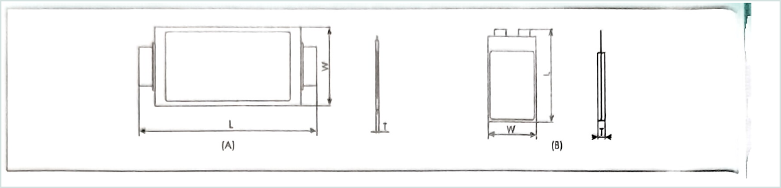
Extracted from page 2 of the supplied LORIDA AA Series datasheet. Dimensions are in millimetres; use the controlled part-number drawing for final enclosure release.
Why This Construction Matters
The soft-pack cell format influences terminal resistance, mounting method, vibration behaviour, heat transfer, polarity control and serviceability. Cell construction gives the system designer more freedom in bank configuration, but requires disciplined interconnect, balancing and retention design.
Best Fit for Buyers
The AA Series is intended for OEMs, power-system integrators, industrial-control suppliers and component distributors that need a traceable electrical window plus part-number-level mechanical verification. It supports early feasibility screening, sample validation, pilot production and controlled release.
01Server Backup Power
Check hold-up duration, peak current, recovery time, thermal environment and available mounting space for this application.
02Communication Terminals
Check hold-up duration, peak current, recovery time, thermal environment and available mounting space for this application.
03Automotive Electronics
Check hold-up duration, peak current, recovery time, thermal environment and available mounting space for this application.
Reliability and Validation Plan
The supplied datasheet defines temperature, load, storage and cycle-related checks for this series. Project approval should add the real duty cycle: maximum steady voltage, transient voltage, charge current, discharge current, pulse frequency, ambient profile, cooling conditions and expected service life. Samples should be measured before and after the agreed electrical and environmental test sequence.
| Validation Step | Engineering Evidence |
|---|
| Electrical baseline | Capacitance, ESR, leakage/self-discharge and terminal polarity at agreed conditions. |
| Duty-cycle test | Actual voltage window, current waveform, recharge interval and repetition count. |
| Environmental check | High/low temperature, storage, vibration and mounting conditions required by the project. |
| Mechanical approval | Envelope, terminals, polarity marking, mounting points, clearances and labeling. |
Engineering RFQ Checklist
Nominal, maximum and minimum operating voltage
Required hold-up time or usable energy
Peak/continuous current and complete pulse waveform
Charge method, recharge time and cycle frequency
Ambient temperature, cooling and enclosure conditions
Maximum dimensions, terminal orientation and mounting constraints
Target lifetime, annual demand, sample quantity and qualification schedule
Label, LORIDA branding, packaging and documentation requirements
Discuss the AA Series with LORIDA
Send the electrical waveform and mechanical envelope. Our engineering team can screen the suitable series window and prepare a part-number-level quotation, drawing review and sample plan.
Request an Engineering ReviewFrequently Asked Questions
How do I calculate the required capacitance?
Use the usable-energy equation with the real start and end voltages, then include load power, converter efficiency, ESR drop, temperature and ageing margin.
Can several devices be connected in series?
Yes, but the effective capacitance falls and voltage sharing must be reviewed. Use conservative per-device voltage limits and an appropriate balancing strategy.
What determines pulse-current capability?
ESR, terminal resistance, conductor design, pulse duration, repetition rate and thermal conditions all matter. Provide the complete waveform for review.
Can dimensions and terminals be customized?
Mechanical feasibility can be reviewed together with voltage, capacitance, temperature window, module configuration, labeling and order requirements.
What is needed before sample approval?
Confirm the part-number datasheet, controlled drawing, polarity, mounting, electrical duty cycle, environmental conditions and agreed validation plan.




