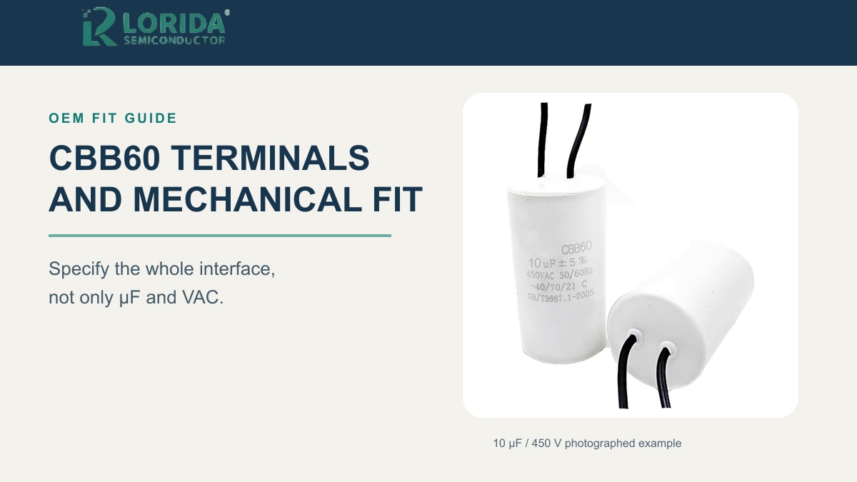
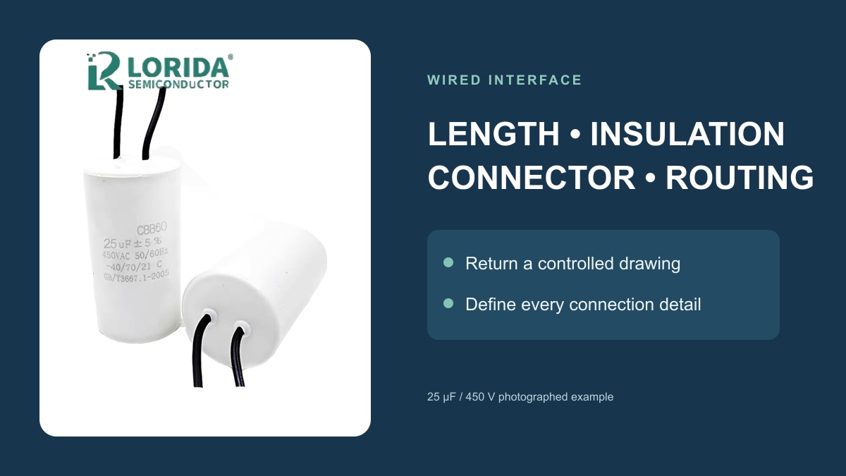
A CBB60 motor-run capacitor RFQ should define the electrical rating and the complete mechanical interface: body diameter and height, lead or terminal style, wire length, connector, mounting method and available clearance. LORIDA’s public CBB60 category shows a 25 µF / 450 V example, while third-party reference families show several different terminal and mounting options. Those examples prove why “CBB60” alone is not a complete fit specification. The exact offered model still needs its own drawing, data sheet and first-article check.
Key Takeaways
Match capacitance, VAC, frequency and motor-run duty before comparing the package.
Record the installed body envelope and connection style instead of ordering from a family name or photograph.
Define lead length, insulation, connector or fast-on geometry in the RFQ.
Approve the exact drawing and first article before production.
Last Updated: September 16, 2026.
1. Why CBB60 fit belongs in the RFQ
One family name can cover several interfaces
CBB60 normally points buyers toward a cylindrical motor-run capacitor, but it does not define one universal body, lead exit or connector. A supplier may offer flexible wires, sleeved cable, single or double fast-on tabs, a plain can or a mounting stud. Two parts with the same capacitance and rated AC voltage may therefore require different assembly work and enclosure clearance.
TDK’s B32320/B32322/B32327/B32328R data sheet is a useful third-party illustration: it separates single fast-on, double fast-on, flexible lead and sleeved-cable constructions. These are TDK examples, not LORIDA series claims. They show which fields belong in a serious RFQ.
Electrical compatibility remains the first gate
Mechanical fit cannot rescue the wrong electrical part. The offered capacitor must meet the motor manufacturer’s required capacitance, tolerance, rated AC voltage, frequency and continuous motor-run duty. The LORIDA CBB60 category presents a 25 µF / 450 V catalogue example, not a universal range.
The cited TDK family lists ±5%, 440 VAC and 50/60 Hz for its own parts, plus reference maximums of 1.1 times rated voltage and 1.3 times rated current. These values must not be copied into a LORIDA specification. They demonstrate that every quoted series needs its own documented electrical limits.
2. Define body, mounting and connection
Measure the available envelope
Record the old capacitor’s maximum body diameter, body height, lead-exit area and any cap, boot or connector height. Then record the real enclosure space, including wire bend radius and service access. A real buyer question distinguished a maximum length of 54 mm from a suggested 60 mm replacement. That wording exposes a common failure mode: a correct electrical value can still be impossible to assemble.
State whether the design uses a clamp, molded clip, adhesive, plain can or threaded stud. If a stud is required, define its thread, length and tightening limit. The TDK reference shows an optional M8 stud and 5 N·m maximum torque; KEMET’s C27 drawing separately shows M8 × 10 examples. These vendor-specific numbers illustrate the required drawing fields, not a LORIDA promise.
Specify wires or fast-on tabs precisely
For wires, define conductor count, finished length, insulation, strip or terminal finish, connector and routing clearance. KEMET’s third-party C27 drawing shows 300 ±10 mm bipolar and 250 ±10 mm polar cable examples. They demonstrate why “with wires” is incomplete: the RFQ must state the measurement datum and whether the connector is included.
For fast-on versions, define tab width, thickness, count, spacing, orientation and mating receptacle. KEMET illustrates a 6.3 × 0.8 mm fast-on example. A buyer who requests only “two terminals” may receive a part that does not mate with the controlled harness.
| RFQ field | Buyer evidence | Supplier return | First-article check |
|---|---|---|---|
| Electrical rating | Motor requirement and old label | Exact value, tolerance, VAC and Hz | Compare label and data sheet |
| Body envelope | Diameter, height and keep-out drawing | Controlled outline drawing | Gauge fit without force |
| Wired interface | Length datum, insulation and connector | Finished lead assembly drawing | Measure and verify mate |
| Fast-on interface | Tab count and receptacle part | Geometry and orientation | Verify insertion and retention |
| Mounting | Clamp, clip, plain can or stud | Mount detail and torque limit | Inspect retention and case stress |
3. Turn the quote into a first-article decision
Separate requirements from offered claims
Use three columns in the sourcing file: buyer requirement, supplier-offered value and verification evidence. Ask the supplier to return the exact part designation, current data-sheet revision, dimensional drawing, lead or terminal drawing, declared standard and every deviation from the RFQ. Printed symbols in a photograph do not prove that the offered production model holds a current approval.
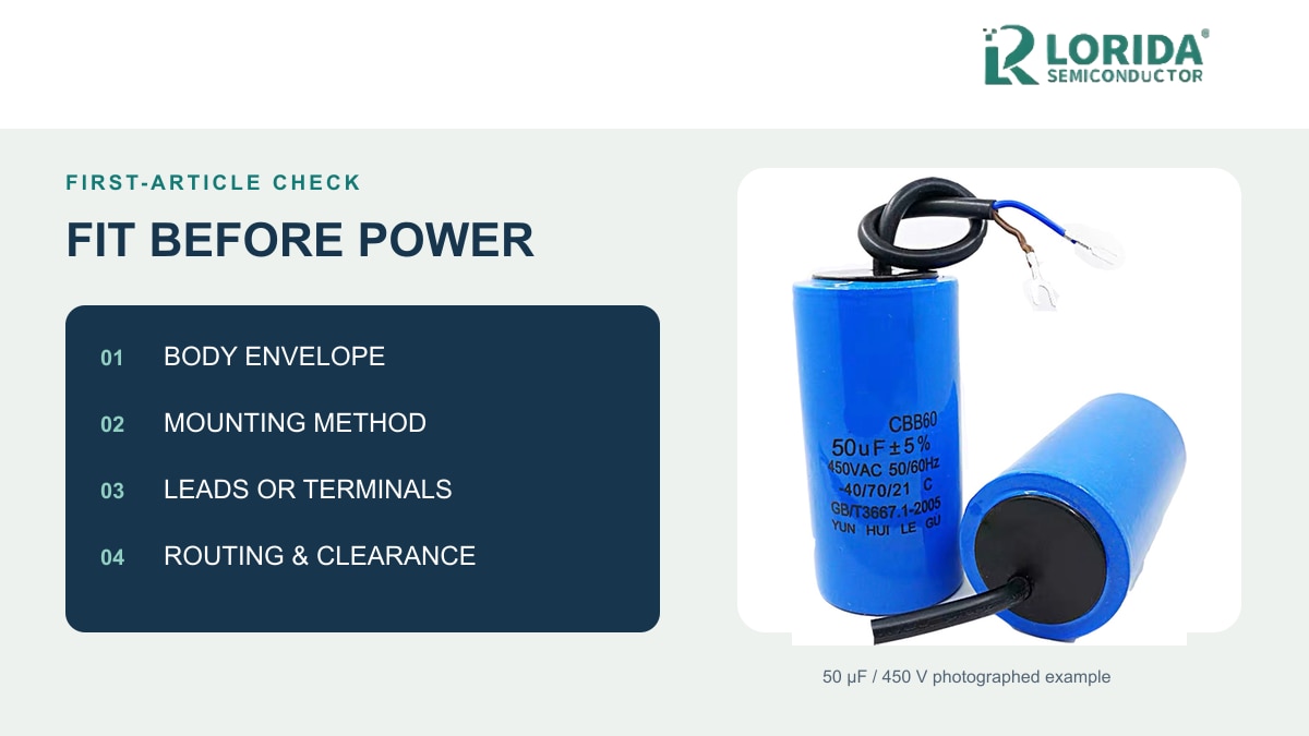
First perform a de-energized incoming inspection: identity, label, capacitance, body dimensions, lead or tab layout, connector fit and mounting retention. TDK’s installation instructions tell users to discharge and short-circuit a capacitor before handling and to avoid excessive vibration, mechanical shock and pressure. Any energized equipment test must follow the equipment documentation and be performed by qualified personnel.
Use a concise approval checklist
Approve production only after the exact quoted construction fits the real motor and enclosure without forcing the case, sharply folding leads or leaving the harness unsupported. Record the sample lot, drawing revision and decision. The separate CBB60 replacement guide covers the broader electrical six-check process; this guide adds the terminal and assembly evidence needed for a buildable quote.
4. Buyer FAQs
Can I replace a wired CBB60 with a fast-on version?
Yes, but only when the OEM approves the new interface and the complete part remains electrically and mechanically compatible. Match capacitance, tolerance, AC voltage, frequency and continuous-duty construction first. Then confirm tab geometry, mating receptacle, insulation, enclosure clearance and wiring diagram. An improvised adapter can add heat, resistance and vibration risk, while the terminal stack may increase the total installed height. Request the exact terminal drawing and inspect the first article in the real assembly. Mains wiring and connector changes must be reviewed and performed by qualified personnel under the equipment instructions.
Do four wires mean two separate capacitance values?
Not necessarily: four wires may represent duplicated connections, multiple sections or another internal arrangement. Color and conductor count alone cannot identify the circuit. Obtain the original appliance schematic and the old capacitor’s full marking, then request an internal-connection diagram for the offered model. Check continuity only with the equipment safely de-energized and the capacitor discharged under the service procedure. The supplier quotation should state every capacitance section, common point and lead identification. If the offered diagram cannot be reconciled with the controlled wiring diagram, hold the sample for engineering review instead of combining wires by appearance.
Is the same µF and 450 VAC enough when the new body is smaller?
No: matching the headline rating does not prove identical duty, safety construction, temperature capability or mounting fit. Obtain the exact-series data sheet, declared standard, tolerance, frequency and environmental limits. Verify that the smaller body can be retained by the existing clamp or clip without excessive pressure and that the lead exit is not under tension. A smaller can may leave the harness unsupported or change service clearance. Approve the offered drawing and first article, not visual similarity, and do not infer longer life or higher current capability from size alone.
What dimensions belong in a CBB60 RFQ?
Include maximum body diameter, body height, mounting details and the complete connection envelope. For wires, add the length datum, insulation, strip or terminal finish, connector and routing clearance. For fast-on versions, add tab width, thickness, count, spacing, orientation and mating receptacle. If a bottom stud is needed, define its thread, length and tightening limit. Provide the available enclosure envelope rather than only the old part dimensions because service access and wire bend radius also consume space. Ask the supplier to return a controlled drawing with tolerances and flag every deviation before samples ship.
5. Request a traceable CBB60 quote
Send the complete interface
Use the LORIDA CBB60 category to identify the relevant family, then attach the motor nameplate, old-capacitor label, connection photographs, controlled envelope, mounting method and wiring diagram.
Send your CBB60 interface requirements
share the electrical duty, lead or tab construction, connector, dimensions, mount and sample acceptance plan through the LORIDA contact page. This lets the response identify a specific model and drawing instead of relying on a family name.
Sources and attribution
LORIDA CBB60 category: product-family context and public 25 µF / 450 V example.
TDK B32320/22/27/28R data sheet: third-party electrical, terminal and stud examples only.
KEMET C27 data sheet: third-party cable, tab and mounting drawing examples only.
TDK installation instructions: handling and installation cautions.