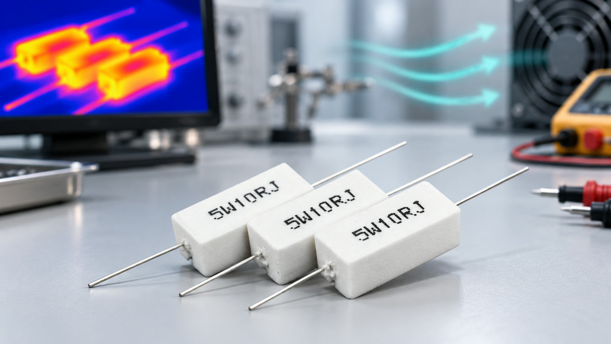
A cement resistor that runs hotter than expected should be diagnosed from electrical dissipation, ambient and enclosure temperature, mounting, airflow, pulse duty and the exact datasheet derating curve—not from case color alone. Published manufacturer data show that ceramic-housed families can span 3 W to 20 W, use different wirewound or metal-oxide elements, and require part-specific overload and temperature limits. This guide gives OEM buyers a six-check process for separating normal heat from an unsafe application.
Key Takeaways
What the investigation must prove
Calculate steady dissipation from measured voltage and current, then add pulse energy and repetition.
Wattage printed on the body is not permission to use that power at every ambient temperature.
Lead spacing, PCB temperature, nearby parts, airflow and enclosure heat change the operating point.
Do not compare case temperature with a generic “safe” number; compare the measured condition with the exact series documentation.
Resistance and wattage alone do not define working voltage, overload behavior, construction or thermal rise.
Infrared readings need emissivity, focus, distance and a repeatable measurement point.
Discoloration, cracking, odor, solder damage or resistance drift requires shutdown and root-cause review.
Why Does a Cement Resistor Overheat?
Electrical power becomes heat
For a resistive load, steady power can be cross-checked as P = VI, P = I²R or P = V²/R. A mismatch between calculated and measured power often reveals a wrong resistance value, an unexpected duty cycle, a waveform measurement problem or a circuit fault. Use RMS voltage and current for the actual waveform; do not apply a DC calculation to a chopped or pulsed load without accounting for time.
Manufacturer ranges show why appearance is not enough. Ohmite publishes its ceramic-housed TWW wirewound family at 3 W, 5 W, 10 W, 15 W and 20 W, while the related TWM parts use metal-oxide elements. The same page lists working-voltage examples from 250 V to 750 V depending on size. These are Ohmite series examples, not universal LORIDA specifications, but they demonstrate that two similar white cases may have different internal construction and limits.
Ambient temperature and installation consume margin
A resistor heats above the air and surfaces around it. If enclosure air is already warm, a nearby semiconductor radiates heat, or the board cannot move heat away, the element reaches a higher temperature for the same electrical power. Ohmite states that the TWM/TWW design keeps generated heat away from the circuit board through its radial-terminal format, yet it still provides a derating curve rather than a blanket wattage claim. That is the correct engineering pattern: use mounting-specific evidence.
Six Checks for a Hot Cement Resistor
1. Confirm resistance and calculate real dissipation
Isolate power, discharge stored energy and confirm the resistance against the approved order code. Then capture the installed voltage and current with instruments that have enough bandwidth for the waveform. Calculate average continuous power and record RMS values, pulse width, repetition rate and worst-case supply tolerance. If the resistor is part of a discharge, brake or inrush path, include the energy stored upstream and the minimum cooling interval.
2. Identify the exact series, element and voltage limit
Request the complete manufacturer, series, resistance, tolerance and construction. Ohmite’s TWW examples use wire elements from 0.01 Ω to 560 Ω depending on size, while TWM metal-oxide examples extend as high as 200 kΩ. The manufacturer also lists 1000 VAC dielectric-withstanding voltage for the family. These values belong only to that cited family; they show why a generic “cement resistor” label cannot approve a substitute.
3. Apply ambient-temperature derating
Read the exact derating graph and reduce allowable power at the real local ambient. Measure air temperature close to the body after the enclosure reaches equilibrium, not only room temperature. Note orientation, spacing to the PCB and neighboring heat sources. Vishay’s CW example publishes characteristic-dependent operating limits and a rated-power curve, illustrating that the permitted load changes with temperature and construction.
4. Separate continuous power from overload duty
Short-time capability is not continuous capability. Ohmite publishes 10× rated power for 5 seconds for TWW and 5× rated power for 5 seconds for TWM, with a different condition for 15 W and 20 W parts. Vishay’s CW data likewise distinguishes parts at or below 3.75 W from parts at or above 4 W in its 5-second overload test. Use only the curve and resistance range for the exact order code.
5. Measure temperature with a repeatable method
Record instrument model, emissivity setting, distance, angle, focus, measurement point and stabilization time. Confirm suspicious infrared results with a suitably attached sensor where safe. Measure the resistor body, lead/terminal region, solder joint, PCB below the part, inlet air and the nearest heat-sensitive component. A single thermal-camera screenshot without method data cannot support sample approval.
6. Inspect damage and verify post-test resistance
After a controlled run and safe cooldown, inspect for cracked ceramic, loose cement, darkening, blistering, odor, lead oxidation, solder degradation and board discoloration. Re-measure resistance with a documented instrument. Vishay’s CW load-life example uses 2000 hours at rated power and 25 °C with a 1.5-hour ON / 0.5-hour OFF cycle and specifies a resistance-change limit for that product. Field tests need their own acceptance criteria, but resistance drift is an important evidence point.
Diagnostic Evidence Table
What each observation can and cannot prove
| Observation | Possible cause | Required evidence | Do not conclude |
|---|---|---|---|
| High body temperature | High continuous power, hot ambient, weak airflow | RMS voltage/current, power calculation, local ambient, exact derating curve | “Defective” from temperature alone |
| Rapid temperature spike | Pulse or surge duty | Waveform, energy, duration, repetition, pulse curve | Continuous wattage covers the event |
| Hot solder joint | Lead spacing, poor joint, local current density | Joint inspection, voltage drop, thermal map, assembly drawing | Resistor body is the only source |
| Cracking or odor | Overload, thermal cycling, mechanical stress | Shutdown, damage photos, resistance drift, fault sequence | Continued operation is acceptable |
| Normal room test, hot enclosure | Ambient and recirculation | Closed-enclosure equilibrium test at worst case | Open-bench approval transfers directly |
How Should an OEM Specify the Replacement?
Send a thermal and electrical evidence pack
Include the original part number and photos; nominal resistance and tolerance; steady voltage and current; RMS and pulse waveform; duty cycle; ambient and enclosure temperature; airflow; mounting and lead spacing; body dimensions; required insulation, overload and failure behavior; and the acceptance method. Review LORIDA’s wirewound resistor category and the earlier wirewound resistor inductance guide before comparing a sample. For a datasheet-based review, use the LORIDA contact page.
Frequently Asked Questions
Is it normal for a cement resistor to feel very hot?
It can be normal for a correctly loaded power resistor to run too hot to touch, but touch is not an approval method. Determine the exact series and calculate installed dissipation, then compare the real local ambient and mounting with the manufacturer’s derating data. Measure temperature using a documented method after thermal equilibrium. Also inspect lead and PCB temperatures because heat can damage nearby materials even when the resistor itself remains within its series limit. If there is cracking, odor, solder degradation, darkening or resistance drift, shut down and investigate rather than treating the heat as normal.
Can I replace a 5 W cement resistor with any other 5 W resistor?
No, equal wattage and resistance do not guarantee an equivalent replacement. Check resistance tolerance, TCR, continuous-power test condition, derating curve, limiting voltage, pulse and overload capability, internal element, inductance, dimensions, lead spacing, insulation and required failure behavior. Two white ceramic packages can contain different wirewound or metal-oxide constructions. Provide the original order code, circuit waveform, enclosure temperature and photographs to the supplier, then test the proposed sample in the production-representative assembly. Purchasing should not approve a visually similar substitute until thermal, electrical and post-test resistance evidence meets documented limits.
Why does the resistor overheat only after the enclosure is closed?
The closed enclosure raises local ambient temperature and can recirculate heat, reducing the margin allowed by the derating curve. Nearby semiconductors, transformers and the PCB may also transfer heat into the resistor. Repeat the test with the final cover, airflow path, orientation, load cycle and worst credible room temperature. Measure inlet air, air beside the resistor, body, leads, solder joints and neighboring components until temperatures stabilize. Compare the result with the exact datasheet and material limits. An open-bench test is useful for debugging, but it cannot prove a closed product will remain thermally acceptable.
What data should I send for a cement resistor overheating review?
Send the original part number, circuit duty and a repeatable thermal record. Include resistance and tolerance, steady and RMS voltage/current, pulse waveform, duration and repetition, supply tolerance, ambient and enclosure temperature, airflow, mounting orientation, lead spacing, board material, nearby heat sources, body dimensions and required safety behavior. Add clear product and board photos plus infrared images with emissivity, distance, angle and stabilization time. Report resistance before and after the test and any cracking, odor or discoloration. This package lets engineering distinguish overload, derating, measurement error, assembly heating and unsuitable substitution without guessing from case appearance.
Sources and Review Note
Primary manufacturer references
Ohmite TWM/TWW ceramic-housed resistor official product data
Vishay cement-coated industrial wirewound resistor selector guide
Numerical examples above belong to the cited manufacturer families and are not LORIDA-wide specifications. Last Updated: October 27, 2026. Technical review used the cited primary sources. No individual author or reviewer name is shown because a confirmed public byline identity was unavailable.
Send the part number, waveform, enclosure temperature, mounting and damage photos through the LORIDA contact page.