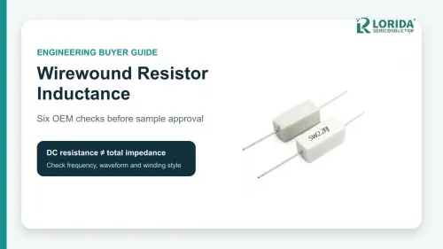
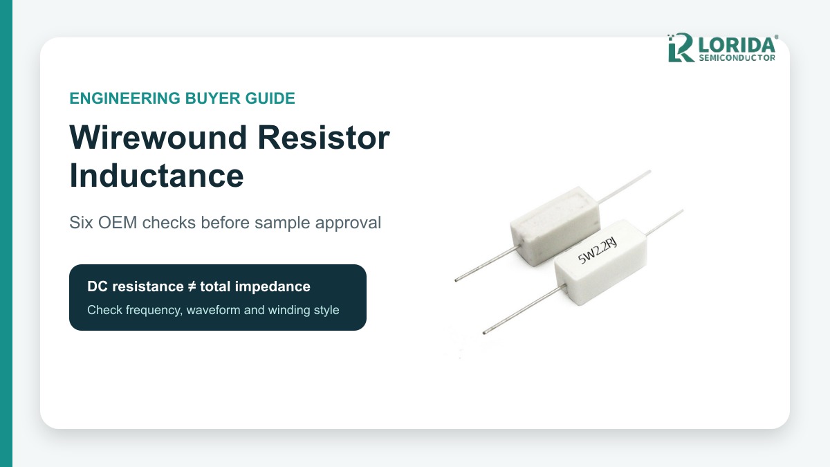
A wirewound resistor should be treated as an R-L component whenever switching speed or frequency makes its winding inductance significant. OEM buyers should define the waveform, request the exact standard or non-inductive construction, and verify impedance and temperature in the installed circuit before approving a sample.
Key Takeaways
What the buyer must prove
DC resistance alone does not describe a wirewound resistor under fast-changing current.
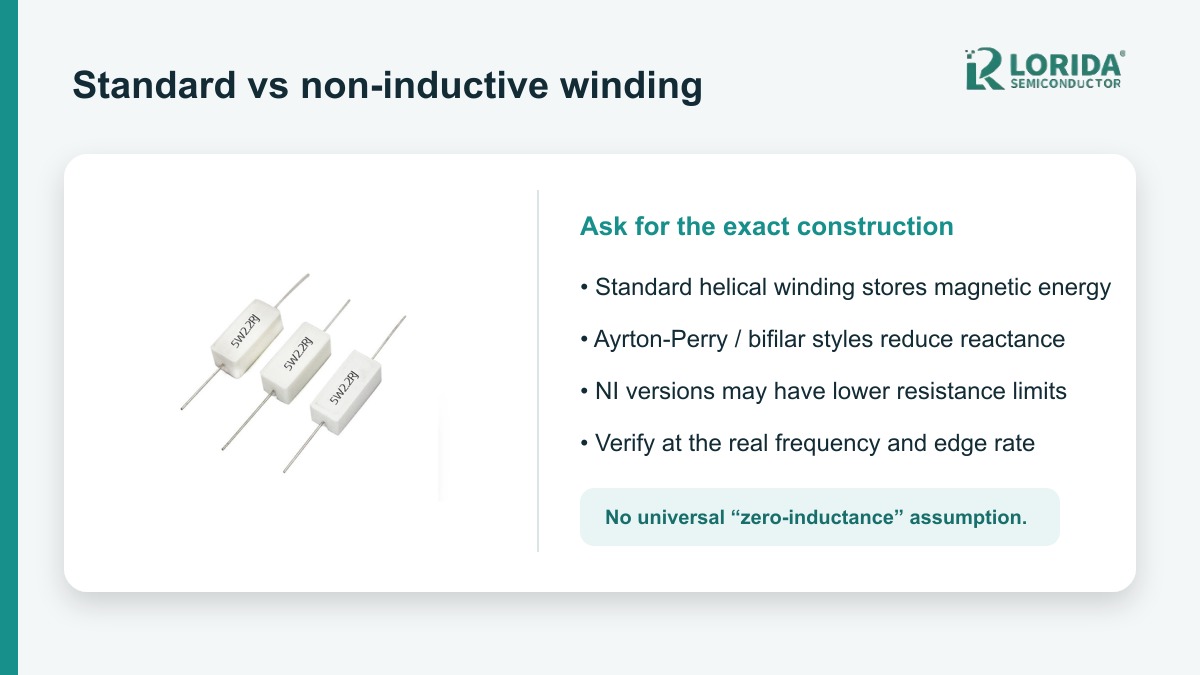
Non-inductive winding reduces reactive behavior, but it does not authorize a universal zero-inductance claim.
Manufacturer examples show that non-inductive versions can have narrower resistance ranges than standard windings.
Frequency, rise time, lead length, loop area, pulse energy and continuous temperature belong in one review.
Final approval should use an installed waveform and temperature test, not only an LCR-meter reading on loose parts.
Why Can a Wirewound Resistor Behave Inductively?
The winding creates a magnetic field
A conventional wirewound resistor is made by winding resistance alloy around an insulating core. That geometry gives useful power and pulse capability, but current through the turns creates magnetic flux. Under DC steady state the inductive voltage falls away, so an ohmmeter reports the intended resistance. During a rapid current change, however, the voltage also contains an L·di/dt component. The result can be extra overshoot, slower current decay, ringing or a shifted damping condition.
The practical question is not whether the component has any parasitic inductance; every physical connection does. The question is whether the total impedance remains acceptable over the actual waveform spectrum. A low-frequency load bank, a motor brake and a snubber can place very different demands on a resistor with the same marked resistance and wattage.
What Does “Non-Inductive” Mean in Datasheets?
Opposing windings reduce reactive components
Vishay identifies several non-inductive options with Ayrton-Perry winding. Its MRP datasheet describes the NI style as providing the lowest reactive components, while the FST datasheet states that equivalent physical and electrical versions are available with an Ayrton-Perry winding. Bourns explains a bifilar approach in which turns run in different directions so their opposing magnetic fields cancel much of the winding inductance.
These descriptions support “reduced” or “minimal” self-inductance, not an assumption of perfect cancellation in every assembly. Lead length, terminal layout, internal spacing and the user’s current loop still contribute parasitic inductance. Buyers should request the exact part number, construction note and test condition instead of accepting a generic “NI” label without evidence.
| Review point | Standard wirewound | Non-inductive option | OEM evidence |
|---|---|---|---|
| Winding | Single helical path | Opposing or Ayrton-Perry paths | Construction code and datasheet |
| Reactive behavior | May be significant at fast di/dt | Reduced, not universally zero | Impedance or waveform result |
| Resistance range | Often broader | Can be narrower | Exact ordering table |
| Approval test | Installed voltage, current and temperature at worst case | Recorded method and limits | |
Six OEM Checks Before Sample Approval
Convert the application into measurable requirements
Define the waveform. State DC or AC level, fundamental frequency, switching frequency, rise and fall time, pulse width, repetition rate and worst-case di/dt. A frequency label alone can miss fast edges that excite the component and wiring.
Specify resistance and tolerance. Include nominal value, tolerance, temperature coefficient and permitted drift. Vishay’s MRP family examples span 0.1 Ω to hundreds of kilohms depending on size and tolerance, so the complete ordering table matters.
Choose standard or NI construction deliberately. Ask the supplier to identify the winding style and any resistance-range tradeoff. Vishay’s AH075 example lists 0.1 Ω to 50 kΩ for the standard version but 5 Ω to 100 Ω for the NI range; this is a series-specific illustration, not a LORIDA-wide specification.
Check power and pulse duty separately. Bourns states that pulse capability depends on resistance-wire mass, wire value and construction. Provide pulse energy, duration, repetition and cooling interval rather than relying on continuous wattage alone.
Control installation geometry. Document body orientation, lead length, terminal spacing, current-loop area, PCB copper, airflow, enclosure temperature and clearance from heat-sensitive parts. External wiring can defeat a low-inductance component choice.
Request repeatable measurements. Define test frequency, fixture compensation, instrument bandwidth, probe placement and acceptance limits. Correlate a component-level impedance test with the installed current and voltage waveform.
Which Published Numbers Are Useful?
Series-specific data illustrates the tradeoffs
Vishay’s FST datasheet lists inductance as varying with wattage and resistance, confirms that non-inductive winding is available, and gives a 10 lb terminal-strength figure. The same document shows a 100% rated-power point at 25 °C with derating to zero at 350 °C for that family. Those figures demonstrate why electrical, mechanical and thermal checks should use the exact series rather than a generic cement-resistor description.
Vishay’s AH family distinguishes chassis-mounted power from free-air capability. The AH075 example is rated 75 W with the specified standard heatsink but 45 W without it; the family operating range is published as -25 °C to +250 °C. These are useful sourcing examples because they show how construction and installation assumptions can change the allowed operating point.
Bourns’ wirewound overview lists axial W, WS and FW series at 1 W to 7 W at 70 °C, with operating ranges extending to +155 °C or +200 °C depending on series. Its technical paper also notes that some custom pulse wirewound models can withstand more than 1000 J, but that figure belongs to named constructions and must never be transferred to an unverified replacement.
How Should Inductance Be Verified?
Use both component and circuit evidence
An LCR meter can provide a controlled comparison if the test frequency, fixture, lead compensation and bias conditions are recorded. The number is incomplete when the real circuit contains faster edges, long leads or a large loop. For switching applications, capture the voltage across the resistor and current through it with adequate bandwidth, then compare overshoot, ringing and settling between candidate parts.
Keep probe loops short and document probe placement. If a non-inductive version changes the waveform but also changes resistance range, thermal behavior or pulse capability, evaluate the complete part rather than only the ringing improvement. Run the test at minimum and maximum input, maximum pulse duty, hot ambient and production-representative mounting.
What Should the Supplier Return?
A part-number-specific evidence pack
Require manufacturer, series, full ordering code, resistance, tolerance, TCR, continuous power condition, pulse or overload data, winding style, inductance or impedance test method, dimensions, lead or terminal details, operating temperature, derating curve and applicable approvals. Ask the supplier to label every value as guaranteed, typical, calculated or measured.
For related sourcing context, review the LORIDA cement resistor category, the cement resistor pulse and thermal guide, and the wirewound resistor pulse-energy guide. Send the original part number, waveform and installation constraints for a model-specific comparison.
Frequently Asked Questions
Is a cement resistor automatically non-inductive?
No; the ceramic or cement package does not by itself prove a non-inductive winding. A cemented part may contain a conventional helical wirewound element, a specially wound NI element or another resistive construction. Request the exact series and ordering code, then check the manufacturer’s datasheet for the winding option and resistance range. If reactive behavior matters, add an impedance or installed-waveform acceptance test. Do not infer winding style from the white case, printed wattage or product photograph. Two outwardly similar parts can have different internal wire, winding patterns, pulse capability and thermal limits.
Can I treat an NI resistor as zero inductance?
No; “non-inductive” normally means that the winding is arranged to reduce net inductance. Residual inductance remains in the element, terminals, leads and surrounding current loop. The effective impedance also depends on test frequency and parasitic capacitance. Ask for the manufacturer’s test method or a frequency-dependent impedance result when available, and verify the installed circuit at the real edge rate. A loose-part LCR result is useful for comparison, but it cannot replace a production-representative waveform measurement with documented probes, layout, temperature and operating voltage.
Why can the NI version have a lower maximum resistance?
Opposing winding paths consume space and impose construction constraints, so the available resistance range can be narrower. Vishay’s FST datasheet explicitly notes lower maximum resistance values for non-inductive models, and the AH table shows different standard and NI ranges for each size. Select from the exact ordering table rather than assuming every standard value is offered in NI form. If the requested resistance is outside the NI range, discuss another size, technology, series or circuit arrangement, then recheck continuous power, pulse duty, tolerance and mechanical fit.
What should be included in a wirewound resistor RFQ?
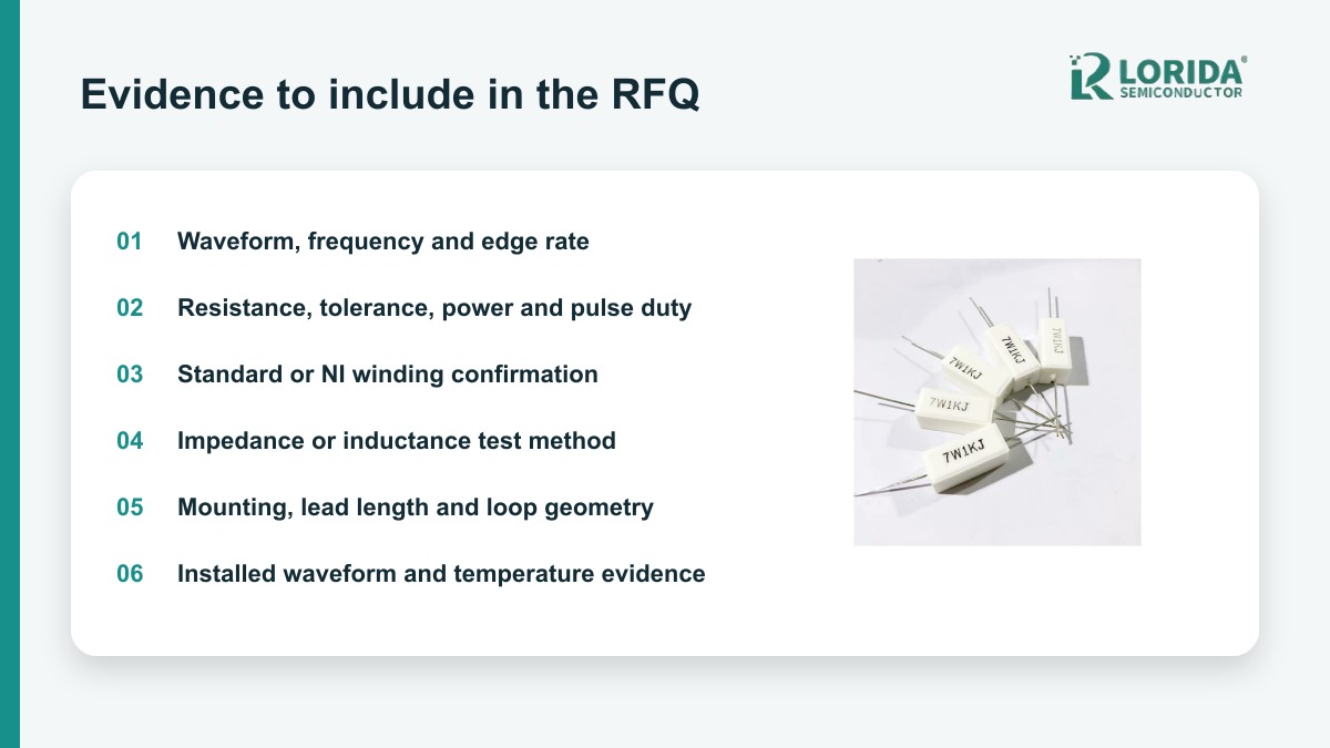
Include the complete electrical waveform and installation, not only resistance and wattage. State nominal resistance, tolerance, TCR, continuous power, pulse energy, duration, repetition, switching frequency, edge rate, ambient, airflow, mounting, lead length, loop geometry and size limits. Identify whether standard or non-inductive construction is required and define how it will be verified. Ask the supplier to return the exact part number, current datasheet, winding description, derating curve, pulse evidence and measured or guaranteed impedance information. This prevents a generic substitute from being approved on appearance alone.
Sources and Review Note
Primary manufacturer references
Last Updated: October 16, 2026. Technical review used the cited manufacturer sources. No individual author or reviewer name is displayed because a confirmed public byline identity was not available.