A DC-link capacitor is thermally acceptable only when its ripple-current spectrum, frequency-dependent losses, temperatures, cooling interface, and allowable dielectric hotspot are validated together. IEC 61071:2017 covers power-electronics capacitors whose system frequency is usually up to 15 kHz, while pulse frequencies may be five to ten times higher. These scope values are not product ratings. Send the real mission profile and require exact-series data, drawings, thermal evidence, and a first-article validation plan.
Last Updated: September 18, 2026
Key Takeaways
The short answer for OEM buyers
Do not approve a DC-link capacitor from capacitance and voltage alone.
Provide ripple current by frequency because ESR and heating change across the spectrum.
Separate ambient temperature, terminal temperature, cooling-surface temperature, and internal hotspot.
Request the exact offered series and construction, not a family-level marketing sheet.
Validate the sample in the real busbar, airflow or cold-plate arrangement before production approval.
Why ambient temperature is not the whole thermal boundary
Terminals can conduct heat into the capacitor
The capacitor sits inside a thermal system. Air temperature around the case matters, but copper terminals and busbars can also conduct heat from semiconductors or other power components. Cooling surfaces may extract heat from one area while a terminal injects heat into another. A single "maximum ambient" number cannot describe that combination.
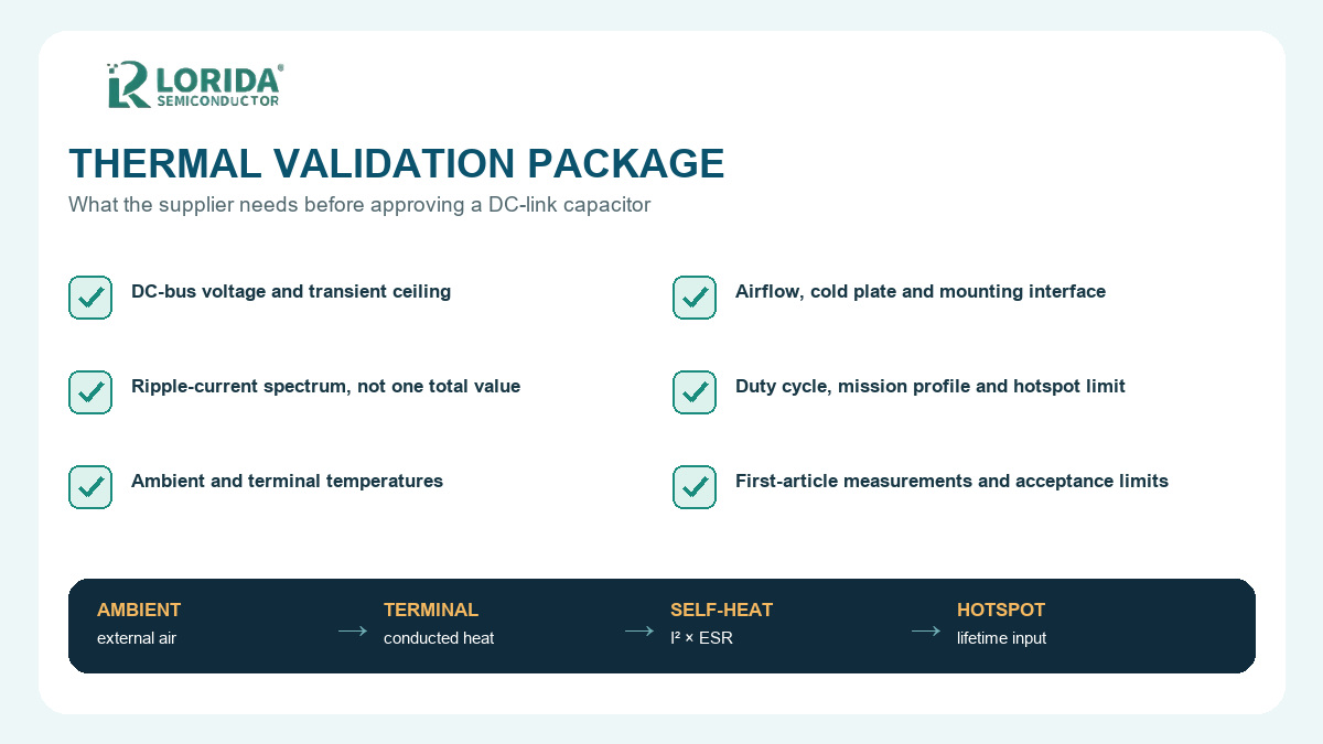
A 2026 TDK white paper models this effect with 35 W of capacitor losses and three terminal boundary conditions: +105 deg C, +115 deg C, and +125 deg C. The example shows why terminal temperature must be treated as an input to the thermal model. These figures describe that simulation, not a safe limit for every capacitor.
The dielectric hotspot is the lifetime input
The critical internal point is normally the hottest part of the dielectric or winding system. It results from external heat, internal losses, current distribution, construction, and cooling. The supplier should define how hotspot is estimated or measured for the offered design. Buyers should avoid converting a case-temperature reading directly into life without the supplier's thermal model or validated correlation.
Translate the electrical mission profile into losses
Send current by frequency, not one RMS number
Converter current contains components at switching frequency, its sidebands, and other harmonics. Since ESR changes with frequency, two applications with the same total RMS current can generate different losses. IEC 61071 notes that system operating frequency is usually up to 15 kHz and pulse frequencies may reach five to ten times that value. That broad scope is exactly why the actual spectrum matters.
Ask the supplier to map each current component to the exact-series ESR or loss model. If only a single catalogue ripple-current value is available, record its test frequency and temperature instead of treating it as universal.
Use product-specific figures only as comparison evidence
TDK's B25696H series announcement illustrates how strongly a rating depends on conditions: it lists up to 91 A at +60 deg C ambient and 10 kHz, a -40 deg C to +85 deg C hotspot range, 100,000 h at +75 deg C hotspot and rated voltage, and up to 200,000 h with derating. These are TDK-series values, not LORIDA ratings. Their value in an RFQ is to demonstrate that current, frequency, temperature, voltage, and life must stay attached to the exact part number.
Use one thermal RFQ table for every supplier
Required inputs and supplier returns
| RFQ field | Buyer provides | Supplier returns | Validation evidence |
|---|---|---|---|
| Voltage duty | Nominal DC bus, maximum steady voltage, transients | Rated voltage and permitted duty | Exact-series data sheet |
| Ripple spectrum | RMS current by frequency and operating mode | ESR/loss model and allowed current | Calculation or simulation |
| External temperature | Ambient, terminal and cooling-interface temperatures | Boundary assumptions | Thermal model inputs |
| Cooling | Airflow, cold plate, thermal pad, mounting contact | Required installation conditions | Controlled drawing |
| Mission profile | Time at each load, voltage and temperature state | Hotspot and life estimate method | State-by-state result |
| Mechanical interface | Busbar, terminal, mount and envelope | Dimensions, torque and keep-outs | Drawing and sample |
| Acceptance | Test points and pass/fail limits | Inspection and first-article plan | Signed report |
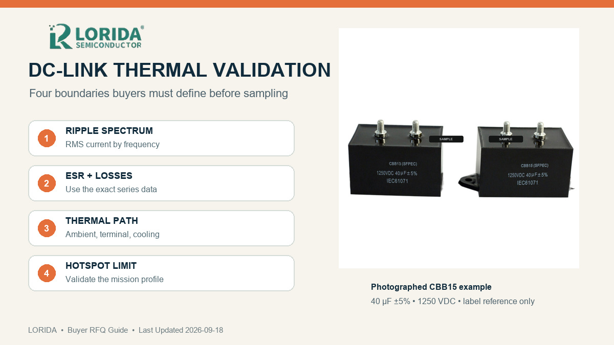
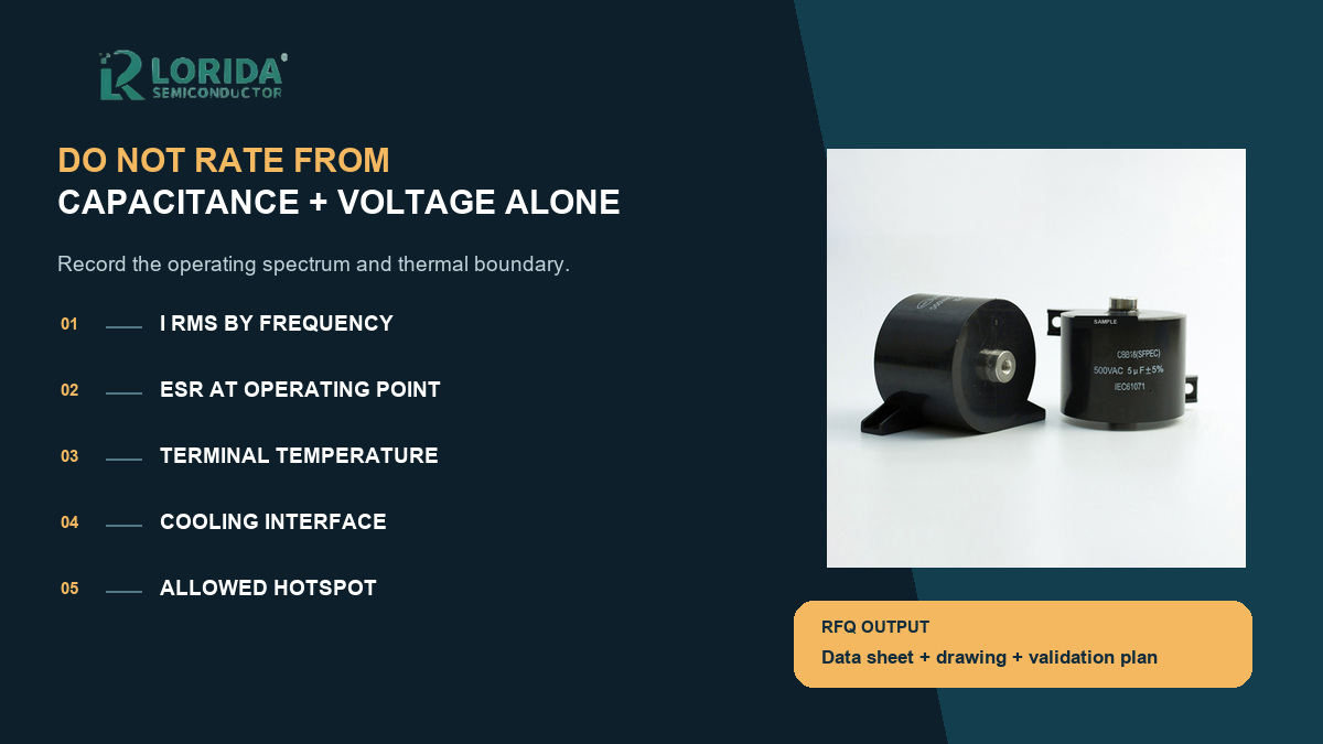
Label discipline: one photographed CBB15 example reads 40 uF +/-5% and 1250 VDC; one photographed CBB16 example reads 5 uF +/-5% and 500 VAC. Both also show IEC 61071. These are two sample labels, not universal family ranges, and a printed standard reference does not by itself prove LORIDA certification.
Define the cooling and mechanical interface
Busbar and mounting details change the result
Terminal geometry affects inductance and heat flow. Send the busbar stack, contact area, tightening method, permitted torque, mounting orientation, nearby heat sources, airflow, cold-plate temperature, and thermal-pad specification. A mechanically compatible part can still run hotter when its contact path differs.
The LORIDA CBB15/CBB16 capacitor category can be used for initial product-family discovery. Final approval still requires the exact offered model's data sheet and drawing. Buyers comparing other constructions can also review the product center and the related DC-link retrofit guide.
Validate the first article on the real converter
Measure the states that drive the hotspot
Use qualified personnel and rated instruments. Record bus voltage, ripple spectrum, ambient, terminal, cooling-surface and defined case temperatures, load, switching condition, and stabilization time. Compare measurements with the supplier model and document sensor or bandwidth limits.
Run the specified worst-case modes and transitions, not only a steady nominal point. Stop the test if the capacitor swells, vents, leaks, arcs, discolors, loosens at a terminal, or exceeds an approved temperature limit. Production approval should freeze the part number, construction, materials subject to change control, drawing, and acceptance plan.
Frequently Asked Questions
Can I select a DC-link capacitor from capacitance and voltage alone?
No. Capacitance and voltage are necessary, but they do not describe heating, current distribution, cooling, or life. Provide the ripple-current spectrum, switching frequency, ambient and terminal temperatures, cooling interface, duty cycle, busbar arrangement, and mechanical envelope. Then require the supplier to return the exact offered series, ESR or loss data at relevant frequencies, a controlled drawing, and a hotspot or life-estimation method. Validate the sample in the real converter. A catalogue family can support discovery, but it cannot replace application-specific electrical and thermal approval.
Why does the supplier need ripple current by frequency?
Because capacitor losses depend on both current and frequency. ESR is not constant across the operating spectrum, so one combined RMS value can hide the components that create the most heat. Send a table or waveform-derived spectrum for each important operating mode, including switching-frequency components and sidebands when available. Ask the supplier to calculate losses with the exact-series model and to state the assumed temperature. If the supplier quotes a single permissible current, keep its specified test frequency, ambient or hotspot condition, cooling setup, and voltage attached to that number.
Is case temperature the same as capacitor hotspot temperature?
No. Case temperature is a surface measurement, while hotspot temperature refers to the warmest internal dielectric or winding region used in thermal and life evaluation. Their difference depends on internal construction, losses, airflow, mounting, terminals, busbar heat flow, and cooling contact. A surface sensor remains valuable, but its location and correlation to hotspot must be defined. Ask the supplier for the thermal model or validated relationship used for the exact part. Do not apply a generic temperature offset from another series or another mechanical installation.
What should be included in a DC-link capacitor sample request?
Include the DC-bus voltage range, transient ceiling, capacitance target, ripple-current spectrum, switching conditions, ambient and terminal temperatures, airflow or cold-plate data, mission profile, busbar drawing, terminal and mounting details, envelope, standards required by the destination market, and acceptance limits. Request an exact part number, current data sheet, controlled drawing, construction statement, loss or thermal calculation, sample inspection record, and first-article validation plan. If any value is unknown, identify it as an open input instead of replacing it with an assumed "typical" condition.
Send a controlled thermal specification
Turn operating data into a quotation package
Use the RFQ table as the cover sheet and attach the converter operating states, mechanical drawing, and test plan. This keeps every supplier response comparable and prevents a family-level rating from being mistaken for approval of the offered model.
Send your DC-link capacitor operating profile
Include the voltage duty, ripple spectrum, temperatures, cooling interface, busbar drawing, mission profile, and validation targets for a model-matching discussion.
Sources
Verified references for exact figures
IEC 61071:2017 official publication page: https://webstore.iec.ch/en/publication/27220
TDK B25696H series announcement: TDK DC-link capacitor article
TDK white paper, Practical Use of Power Film Capacitors: TDK white paper PDF
LORIDA CBB15/CBB16 category: https://www.loridacapacitor.com/cbb15-cbb16-capacitor/