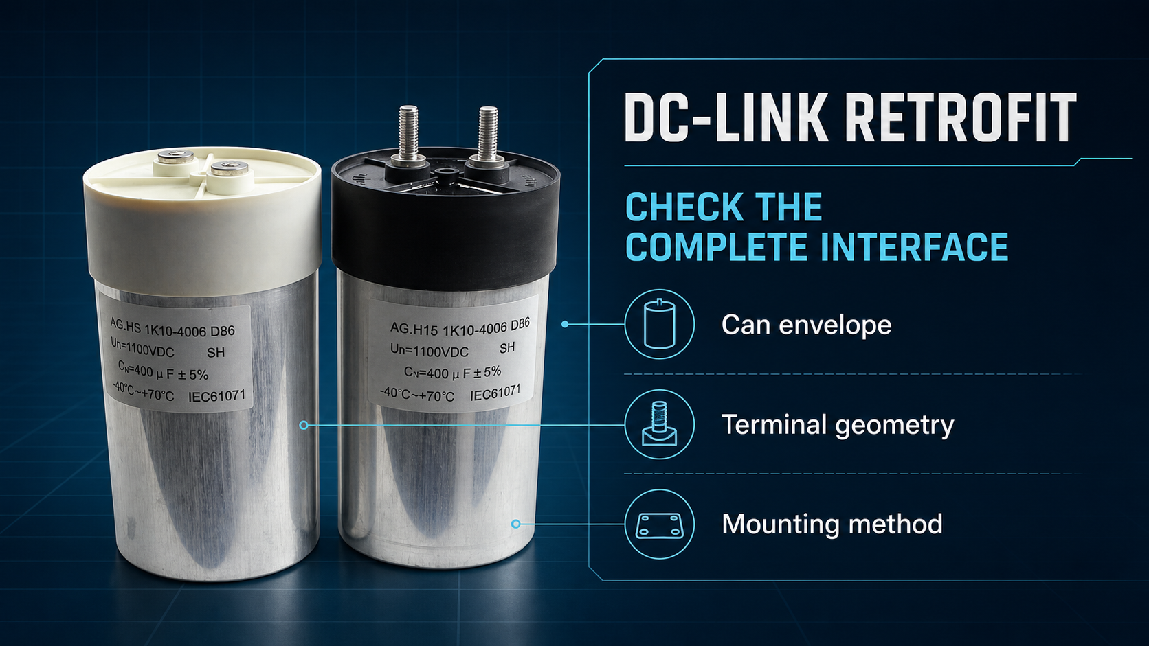
A cylindrical DC-link capacitor retrofit is safe only when the replacement matches the electrical duty and the complete mechanical interface - not capacitance and voltage alone. Before requesting a sample, record the can diameter and height, terminal type and pitch, mounting stud, busbar geometry, clearances, allowable tightening torque, cooling, and the original operating conditions. A replacement that fits the voltage line on a datasheet can still fail to install, stress the lid, distort a busbar, or run too hot.
Last Updated: September 19, 2026
Key Takeaways
What a buyer should send before asking for a substitute
Send the original nameplate, datasheet, and dimensioned drawing instead of only a part number.
Measure diameter, total height, terminal center spacing, terminal thread and usable depth, bottom stud, and keep-out areas.
Describe maximum DC voltage, ripple-current spectrum, ambient and hot-spot conditions, cooling, surge duty, and expected life.
Do not copy a torque value between series. The capacitor manufacturer, fastener, busbar stack, and assembly drawing must agree.
Approve a first article through dimensional, electrical, thermal, and vibration checks before releasing production quantities.
Why the Same Capacitance Does Not Make a Drop-In Replacement
Electrical equivalence and mechanical equivalence are separate gates
A DC-link capacitor works inside a converter, inverter, drive, energy-storage system, or other power stage. Its electrical selection depends on more than nominal capacitance: the replacement must tolerate the real DC voltage, ripple current by frequency, transient stress, ambient temperature, hot-spot temperature, and expected service life. Our earlier DC-link film capacitor selection guide explains that electrical gate in more detail.
The retrofit gate is different. Two capacitors can have similar electrical ratings while using different can diameters, heights, terminal pitches, thread depths, or mounting arrangements. Manufacturer documentation illustrates the spread. KEMET's C44U-T drawing includes 85, 116, and 136 mm can diameters. In that family, the 85 mm can uses a 32 mm terminal pitch, while the 116 and 136 mm versions use 50 mm. These are KEMET series examples, not universal dimensions and not LORIDA standard specifications.
TDK's B25695E announcement gives another concrete example: its cylindrical cases are 85 or 116 mm in diameter, with M6 screw terminals and an M12 threaded bolt on the bottom. The same source lists a 700-1300 VDC rated-voltage range and requires voltage derating above 85 deg C. Those values describe that TDK series only. Their value in a retrofit guide is to show why the buyer must identify both the electrical operating point and the physical interface.
The Seven Mechanical Checks Before Sampling
1. Record the full envelope and installation keep-out zones
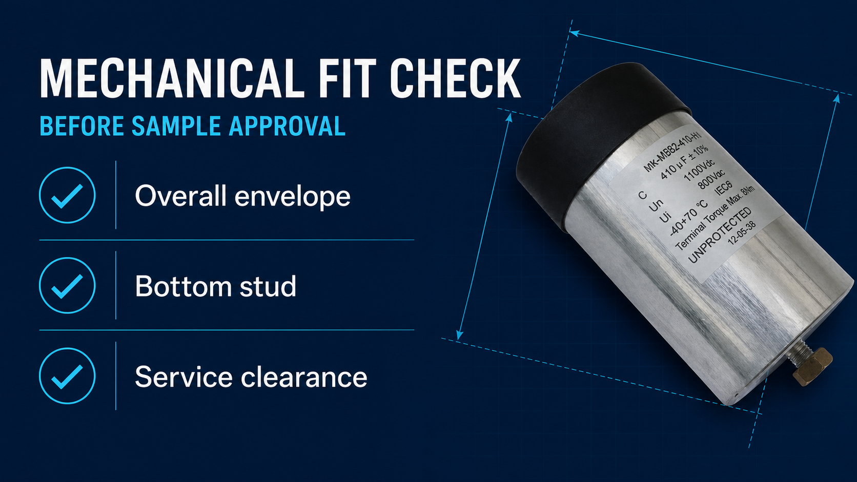
Measure the maximum permitted diameter and height with the original capacitor installed. Include the lid, terminals, washers, lugs, busbar, bottom stud, insulation barriers, and the clearance needed for tools. A nominal can size is not the entire installed envelope. Photograph the part from the top, side, and mounting surface with a ruler or caliper visible, then attach a drawing with tolerances.
Do not assume that a smaller can is automatically acceptable. A smaller diameter may move the terminal centers, reduce clamp support, alter cooling airflow, or leave a bottom stud unsupported. A taller replacement may meet the panel dimension but violate creepage, clearance, door, or service-tool access. State the mounting orientation and nearby conductive surfaces in the RFQ.
2. Identify female inserts, male posts, thread size, and usable depth
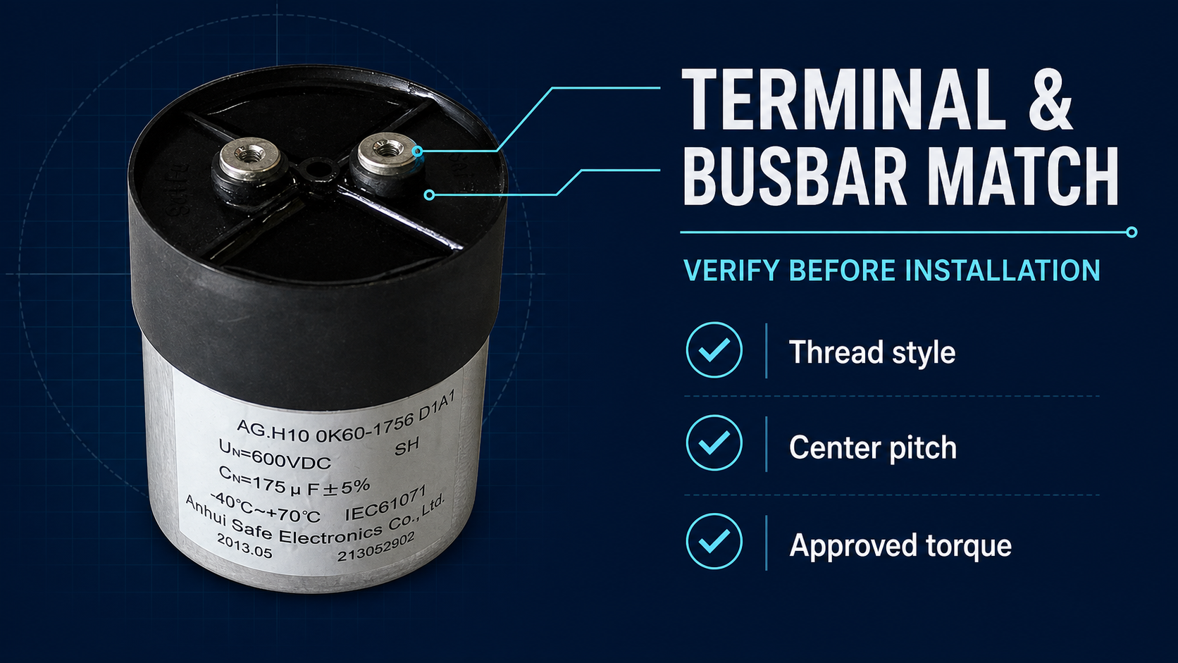
Write the terminal interface exactly: female threaded insert or male threaded post, metric thread size, usable thread depth or post length, and the supplied hardware. A label such as "screw terminal" is insufficient. The KEMET C44U-T family, for example, documents M6 x 10 threaded inserts and M8 x 20 threaded posts as alternative termination styles, together with an M12 x 16 mounting stud. Jianghai's 2025 film-capacitor catalogue shows still more order-code choices, including female and male terminal variants. These examples demonstrate that thread geometry is a selectable attribute, not a safe assumption.
Also identify the washer stack, lug thickness, plating compatibility, and minimum thread engagement specified by the selected supplier. A bolt that is too long can bottom out before clamping the busbar. A bolt that is too short may provide inadequate engagement. The assembly drawing - not a visual guess - must control the hardware.
3. Measure terminal pitch and busbar-hole geometry
Measure terminal center-to-center pitch in both axes and show the tolerance. Include busbar-hole diameter, slot dimensions, conductor thickness, insulation film, bend location, and the distance from the capacitor lid. The retrofit should not require the busbar to spring sideways or downward to reach the terminals.
Published series demonstrate why this matters. KEMET lists 32 mm pitch for certain 85 mm C44U-T cans and 50 mm for the larger cases. Jianghai's catalogue also shows 32 and 50 mm options in its cylindrical DC-link order structure. Matching "M6 terminals" therefore does not prove that the busbar holes will align. Pitch, height, and terminal style must be checked together.
4. Verify the bottom stud, bracket, clamp, and anti-rotation method
State whether the original part uses a bottom threaded stud, flat base, side clamp, flange, or a custom bracket. Record the stud thread, exposed length, mounting-hole diameter, washer and nut stack, and the permitted torque. If the can must not rotate during busbar assembly, show the anti-rotation feature or holding method.
A bottom stud is not just a convenient locator. It carries mechanical load and can influence thermal contact and vibration response. TDK's cited series uses an M12 bottom threaded bolt, and KEMET lists M12 x 16 in its relevant dimensional table. Jianghai's order code includes both flat mounting and several stud-bolt choices. A replacement should not be approved from the top view alone.
5. Assign torque values to the exact series and joint
Torque must come from the selected capacitor datasheet or an approved supplier drawing, then be reconciled with the busbar and fastener specification. It must never be copied from a different series. KEMET gives maximum driving-torque examples of 4 Nm for a female M6 terminal and 7 Nm for a male M8 terminal in the C44U-T document. Jianghai lists maximum terminal-torque examples of 3, 5, 6, and 8 Nm for M5, M6, M8, and M10 respectively in one catalogue section. Exxelia's DCL-41 drawing gives 6 Nm for its M6 x 12 version, 9 Nm for its M8 x 20 version, and 10 Nm for the M12 mounting point.
Those different values are the warning: thread size alone does not determine the approved assembly torque. Record who owns the torque value, the tool calibration requirement, tightening sequence, whether a counter-hold is required, and whether the joint needs witness marking or reinspection.
6. Check creepage, clearance, insulation, and lid loading
Overlay the proposed replacement drawing on the original assembly. Confirm air clearance and creepage around both terminals, the busbar, cabinet, heatsink, clamp, and mounting hardware. Include the system voltage, pollution environment, insulation concept, and applicable equipment standard so the responsible engineer can set the required distances.
The busbar must sit naturally on the terminals. Do not force it into position with the terminal bolts, because that can transmit bending or torsional load into the lid and terminal seals. Confirm that washers and lugs remain inside their intended contact surfaces and do not reduce clearance. If an insulating cover is used, check its fit with the final busbar stack.
7. Validate cooling, vibration, and service access in the real assembly
Mechanical fit is not complete until the first article is tested in the intended orientation and cooling environment. Record ambient temperature, airflow direction, neighboring heat sources, base contact, clamp contact, and the measured capacitor case or hot-spot proxy at worst-case load. Compare the measured temperature with the selected supplier's ripple-current and lifetime model.
For mobile, traction, wind, or high-vibration equipment, define the equipment-level vibration and shock requirement and confirm how the capacitor is supported. Check that cables or busbars do not transfer repeated loads to the terminals. Finally, verify that a torque tool can reach the fasteners and that the capacitor can be removed without disturbing unrelated high-voltage parts.
Retrofit RFQ Comparison Table
Use one controlled drawing instead of scattered email measurements
| RFQ field | What to provide | Why it blocks a drop-in decision |
|---|---|---|
| Electrical duty | Maximum DC voltage, ripple spectrum, surge duty, ambient/hot-spot, life target | Nominal capacitance does not establish current, thermal, or lifetime capability. |
| Can envelope | Diameter, body height, total installed height, tolerances, keep-out zones | A nominal case code may omit terminals, hardware, and service clearance. |
| Power terminals | Female/male style, thread, depth/length, pitch, polarity marking if applicable | Thread size alone does not guarantee busbar alignment or engagement. |
| Mounting | Bottom stud or flat base, bracket/clamp, orientation, anti-rotation method | The mounting path controls support, vibration, and assembly access. |
| Busbar joint | Hole/slot drawing, conductor stack, washers, plating, approved torque source | Forced alignment or wrong torque can damage the terminal or lid. |
| Insulation | System voltage, required creepage/clearance, barriers and cover drawing | A geometrically fitting part can still violate the equipment insulation design. |
| Validation | Incoming dimensions, electrical test, thermal run, vibration check, first-article approval | Production release requires evidence in the real assembly. |
A Practical First-Article Validation Plan
Approve the replacement in four controlled stages
Stage 1 - document review: compare the original datasheet, replacement datasheet, dimensioned drawings, and the equipment assembly. Mark every difference. If the original part is obsolete and documentation is incomplete, treat measurements from the removed part as inspection data, not as the manufacturer's guaranteed tolerance.
Stage 2 - incoming inspection: measure case diameter and height, terminal pitch, thread, usable depth, bottom stud, and relevant insulation features. Confirm labels and lot traceability. Use a thread gauge and calibrated dimensional tools rather than test-fitting unknown hardware.
Stage 3 - assembly trial: install the capacitor with the approved hardware and torque process. Verify that the busbar sits flat without preload, the anti-rotation method works, clearances remain acceptable, and all tools can be removed safely. Photograph the completed joint and record torque-tool identification.
Stage 4 - powered validation: run representative and worst-case operating points under the equipment owner's safety procedure. Record DC voltage, ripple current, ambient and capacitor temperature, abnormal noise, and any protection events. A supplier can help match a component, but the equipment manufacturer remains responsible for validating the complete high-voltage assembly.
For a sample discussion, send LORIDA the completed comparison table, original part data, installation drawing, waveform or ripple spectrum, temperature conditions, and quantity plan. Browse the LORIDA DC-link capacitor category or review the available DC-link film filter capacitor product page as a starting point; final model matching still requires project-specific confirmation.
Frequently Asked Questions
Can I replace a DC-link capacitor with the same capacitance and voltage?
No. The same nominal capacitance and voltage do not prove that a capacitor is electrically or mechanically interchangeable. Compare maximum continuous and transient voltage, ripple current by frequency, ESR, thermal limits, lifetime assumptions, case size, terminal style, terminal pitch, thread depth, mounting method, and insulation clearances. The selected supplier's datasheet must be evaluated against the real converter conditions. Then validate a first article in the actual assembly. If the original part is obsolete, provide its datasheet, photos, measurements, busbar drawing, operating waveform, ambient temperature, cooling, and failure history so the replacement decision is based on controlled evidence rather than a two-line rating match.
Is an M6 terminal enough information for a replacement RFQ?
No. "M6 terminal" leaves several fit-critical details unknown. Specify whether it is a female insert or male post, the usable thread depth or post length, terminal center spacing, terminal height, washer and lug stack, plating, bolt grade, and the torque value approved for the exact capacitor series. Also provide the busbar-hole or slot drawing and show whether the busbar is rigid or flexible. Published manufacturer drawings show that products with M6 terminals can use different pitches, can diameters, heights, and torque limits. A supplier therefore needs a dimensioned interface drawing before confirming that a proposed sample is mechanically compatible.
Can I reuse the original terminal-bolt torque?
Only if the replacement manufacturer and the equipment assembly specification both approve it. Torque limits vary by terminal construction and series, even when the nominal thread size is the same. The busbar material, washer stack, fastener, lubrication or coating, thread engagement, and counter-hold method also affect the joint. Request the replacement datasheet or approved drawing, identify whether the stated value is a maximum or an assembly target, and create a controlled tightening instruction. If the original torque is undocumented, do not derive a new value from thread size alone. Resolve the joint with the capacitor supplier and equipment engineer before the powered test.
What should be measured on an obsolete capacitor?
Measure the complete installed interface, not only the aluminum can. Record body diameter, body height, total height, terminal center spacing, thread type and usable depth, bottom-stud dimensions, bracket or clamp location, polarity or terminal identification, busbar-hole geometry, washer stack, nearby barriers, and tool-access clearances. Take top, side, and mounting-surface photographs with a scale. Also preserve the nameplate, original drawing, application voltage, ripple-current information, cooling, ambient temperature, and observed failure mode. Measurements from an aged part may not equal the original manufacturing tolerance, so label them as observed values and agree acceptable replacement tolerances separately.
When is a retrofit sample ready for production approval?
A sample is ready only after document, dimensional, assembly, and powered validation have all passed with recorded results. The busbar should sit flat without forced alignment; terminal and mounting torque must follow the approved process; creepage and clearance must meet the equipment design; and thermal behavior must be acceptable at representative worst-case load. For vibration-sensitive equipment, include the applicable mechanical test or an approved engineering assessment. Record the replacement part and lot, measured dimensions, assembly photographs, torque-tool identification, electrical test data, temperatures, deviations, and approval authority. A successful bench fit by itself is not sufficient evidence for production release.
Send your cylindrical DC-link retrofit requirements
Include the original datasheet, dimensioned assembly drawing, busbar interface, operating voltage, ripple-current spectrum, temperature and cooling conditions, and first-article quantity for a model-matching discussion.