

A film capacitor's dV/dt limit is the maximum permitted voltage change per microsecond, and OEMs must check it against the measured terminal waveform before approving a pulse application. TDK defines peak current as capacitance multiplied by dV/dt, while Panasonic warns that pulse-current heating can damage the contact between the metallized film and sprayed end connection. The six checks below connect waveform evidence, the exact series datasheet, repetition rate, temperature, mechanical layout and RFQ documentation.
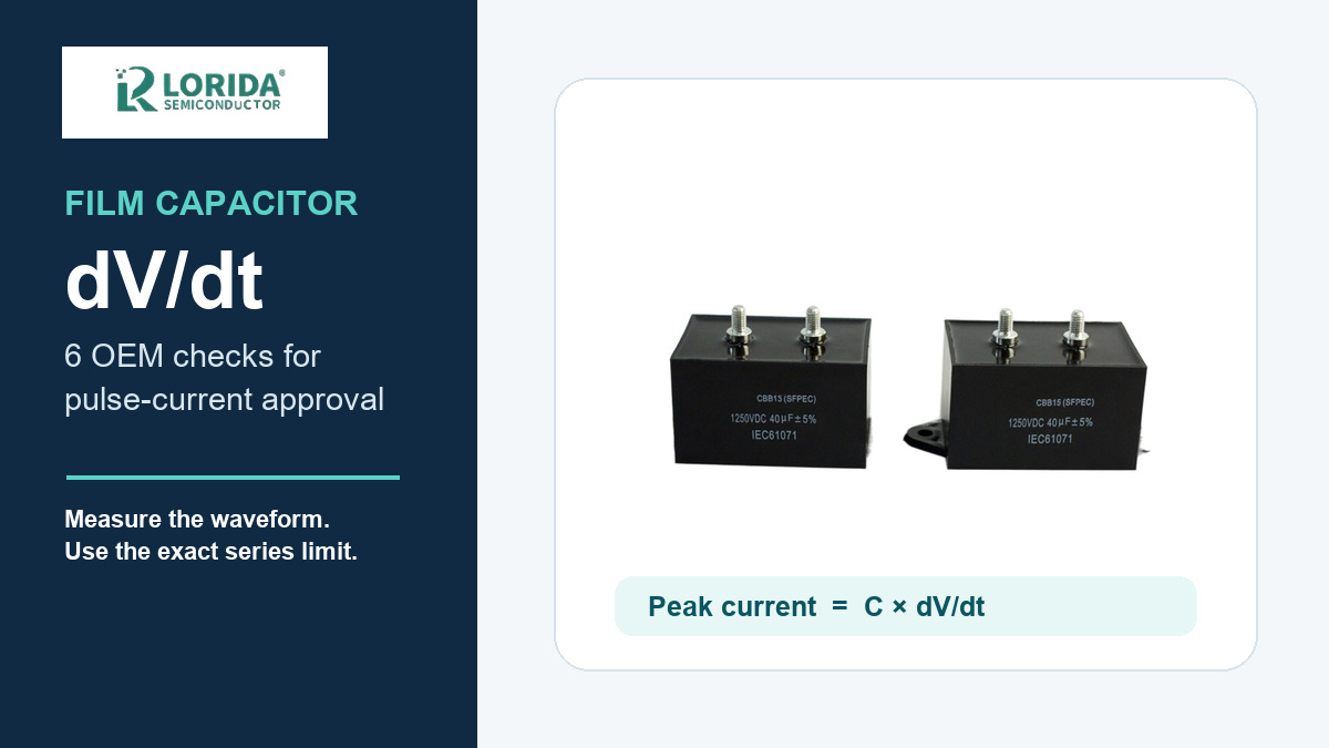
Calculate peak current from the measured slope at the capacitor terminals: i = C × dV/dt.
Use the dV/dt and k0 limits for the exact part number, voltage and lead spacing.
An isolated-pulse limit does not automatically approve a repetitive switching waveform.
Record frequency, case temperature, RMS current and mechanical layout in the RFQ.
What does dV/dt mean for a film capacitor?
Voltage slope creates peak current
For a capacitor, current follows i = C × dV/dt. TDK's film-capacitor technical guide rearranges the same relationship as dV/dt = ip/C, where ip is peak current and C is capacitance. Using compatible units, a 0.22 µF capacitor exposed to 37 V/µs produces about 8.14 A peak. Panasonic publishes a closely related worked example for a 0.22 µF, 400 VDC part with a 37 V/µs limit and reports an 8 A permissible pulse current for the stated conditions. The calculation is useful, but the permissible slope still comes from the exact series specification.
Contact heating sets a practical limit
Fast pulses force current through the connection between the film metallization and the sprayed end contact. TDK explains that excessive pulse energy heats this region and can damage it. Panasonic adds that local heating can reduce capacitance or produce an open circuit, and in severe cases may contribute to smoke or ignition. A voltage rating alone therefore cannot qualify a film capacitor for snubber, resonant, discharge or other high-slope service.
Which six checks should an OEM complete?
Checks 1–2: waveform and exact series limit
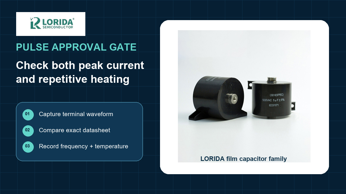
Capture the terminal waveform. Measure directly across the capacitor during startup, steady operation, shutdown, hot restart and credible faults. Record positive and negative slopes, peak voltage, pulse width and ringing.
Match the exact datasheet row. Confirm capacitance, rated voltage, lead spacing, case size and construction. TDK's B3267 series, for example, lists different dV/dt values by voltage and lead spacing: the 450 VDC entries shown are 140, 120 and 100 V/µs for 10, 15 and 22.5 mm spacing. Those numbers demonstrate why a family name is not enough; they are not LORIDA ratings.
Checks 3–4: peak current and pulse energy
Calculate peak current. Apply i = C × dV/dt to the worst measured slope. Compare the result with the series peak-current limit and include tolerance where the manufacturer requires it.
Check k0 or the specified pulse characteristic. TDK uses k0, expressed in V²/µs, to account for waveform energy rather than peak current alone. In the cited B3267 table, the 450 VDC values are 126,000, 108,000 and 90,000 V²/µs for 10, 15 and 22.5 mm lead spacing. The applied waveform must stay below the applicable part limit.
Checks 5–6: repetition, temperature and layout
Evaluate repetitive heating. TDK notes that its cited k0 treatment assumes enough time for heat to dissipate between pulses and calls for derating when repetition exceeds 10 kHz. Panasonic's general example defines its pulse-current figure for up to 10,000 operations and separately requires RMS current to remain within the permissible value.
Validate the built assembly. Check case temperature, ambient temperature, RMS current, busbar or lead inductance, creepage, clearance and mounting stress. Long loops can create ringing and a steeper local waveform than a schematic suggests.
How should buyers document dV/dt in an RFQ?
Send evidence instead of a generic pulse claim
An RFQ should include the circuit function, measured voltage waveform, peak positive and negative dV/dt, pulse width, repetition rate, RMS current, peak voltage, expected case temperature, ambient range, capacitance, tolerance, target life, lead spacing, mounting method and available envelope. Link each waveform to the operating mode that produced it. If the design team has only simulated results, label them as simulations and define the first-article measurements required before release.
Use a release table across engineering and sourcing
| Control point | Evidence | Release rule |
|---|---|---|
| Peak slope | Terminal waveform with sign convention | Below exact-part dV/dt limit |
| Peak current | C × measured dV/dt | Below specified peak-current limit |
| Repetition | Frequency, duty and pulse count | Repetitive rating or derating verified |
| Thermal | Case temperature and RMS current | Within manufacturer limits |
| Mechanical | Drawing, spacing and loop layout | Approved build matches the RFQ |
How do construction and layout change pulse capability?
Construction affects the current path
KEMET describes pulse capacitors as polypropylene film devices intended for high dV/dt and ripple-current service. Its overview distinguishes single-metallized construction, which supports self-healing and high energy density, from double-metallized construction, which offers higher dV/dt and current capability. That comparison is directional, not permission to substitute one series for another. The buyer still needs a current datasheet and drawing for the ordered part.
Lead spacing is an electrical parameter
Lead spacing changes more than PCB fit. The TDK B3267 example shows dV/dt falling as spacing increases for the listed variants because construction and geometry differ. Procurement should therefore prevent an unreviewed pitch or case-size substitution. Engineering should also minimize the commutation loop so parasitic inductance does not add ringing, overshoot or a higher local slope at the capacitor terminals.

What should first-article validation include?
Measure the worst operating modes
Validate minimum and maximum input, light and full load, startup, commanded shutdown, emergency stop, hot restart and the relevant fault recovery. Use probe placement that does not materially enlarge the switching loop. Save screenshots and waveform data with the hardware revision, firmware revision, temperature and load condition. A single normal-load trace cannot prove compliance across all modes.
Keep purchasing limits tied to engineering evidence
The approved vendor list should reference the exact series or an engineering-controlled equivalence process. A replacement may share capacitance and voltage yet have different dV/dt, peak current, k0, RMS current, dimensions or lead spacing. If the waveform changes after a firmware or power-stage revision, repeat the validation and update the RFQ evidence.
Frequently asked questions
Is a film capacitor's voltage rating enough for a snubber application?
No, voltage rating alone does not qualify a film capacitor for a snubber application. The designer must also check the measured dV/dt, peak current, pulse characteristic or k0 where specified, repetition rate, RMS current and temperature. A capacitor can remain below its rated voltage while excessive pulse current overheats the metallized contact region. Use the exact series datasheet and validate the waveform at the capacitor terminals in the assembled circuit. Include startup, shutdown and fault events because their slopes can exceed the steady-state waveform.
How do I calculate film-capacitor peak current from dV/dt?
Calculate peak current with i = C × dV/dt using compatible units. When C is expressed in microfarads and dV/dt in volts per microsecond, the numerical result is amperes. For example, 0.22 µF multiplied by 37 V/µs gives about 8.14 A. The formula estimates current from the waveform; it does not create an allowable rating. Compare the result with the current datasheet for the exact part. Use the steepest measured edge, include capacitance tolerance where required, and preserve the waveform file in the approval record.
Can I use an isolated-pulse dV/dt value for repetitive switching?
No, an isolated-pulse value cannot automatically approve repetitive switching. TDK explains that incomplete heat dissipation between pulses can require derating, and its general guide highlights repetition above 10 kHz as a condition needing additional attention. Panasonic also separates pulse-current and continuous RMS-current limits. Provide repetition rate, duty cycle, pulse count, RMS current and measured case temperature so the supplier and design team can evaluate cumulative heating. Confirm whether the published limit applies to isolated pulses, a defined pulse count or continuous operation before releasing the part.
What files should I send for a film-capacitor dV/dt review?
Send the schematic, measured terminal waveform, operating-condition table, candidate datasheet and mechanical drawing. Include positive and negative slopes, peak voltage, pulse width, frequency, RMS current, ambient and case temperature, capacitance, tolerance, lead spacing, mounting method and expected life. Also identify which traces are measured and which are simulated. LORIDA can compare candidate film-capacitor families with those inputs, while final circuit approval remains with the equipment designer. Add hardware and firmware revision identifiers so the evidence can be traced to the exact tested configuration.
Review your pulse-capacitor RFQ
Send the terminal waveform, repetition rate, temperature, target capacitance and mechanical drawing for a film-capacitor quotation review.
Sources
Primary technical documents
Related LORIDA pages: film capacitors, CBB81 pulse capacitors, and DC-link film capacitor selection.
Last Updated: 2026-10-06


