

Film capacitor RMS current must be checked against the actual current spectrum, loss data, ambient temperature, cooling and hot-spot limit for the exact series. A capacitance and DC-voltage match is not enough. RMS current produces resistive heating, while AC voltage and frequency add dielectric loss. Buyers should reconstruct the waveform, calculate both loss terms, apply the supplier's temperature limits and confirm the result in the real assembly before approving a sample.
Key Takeaways
What to confirm before requesting a sample
Provide the RMS current spectrum, not only one headline current value.
Separate RMS-current heating from voltage, frequency and corona limits.
Use the exact series' ESR, dissipation factor, thermal resistance and derating data.
Define ambient temperature, airflow, spacing, enclosure and nearby heat sources.
Measure case temperature and electrical performance in the actual assembly.
Why RMS Current Becomes a Thermal Limit
Current heating and dielectric heating are different
A film capacitor carries alternating current through its terminals, end spray and metallized winding. The resistive part of the loss rises with the square of RMS current. TDK expresses that term as PR = I2 x RS. The dielectric term depends on applied AC voltage, frequency, capacitance and dissipation factor. TDK therefore treats total power loss as the sum of dielectric and resistive loss, not as a single catalog wattage.
This distinction matters when two waveforms have the same RMS current but different frequency content. A higher-frequency spectrum can change ESR, terminal loss and dielectric heating. Ask for the harmonic or switching spectrum in frequency bands and use the supplier's frequency-dependent data. Do not assume that a 10 A value at one frequency is interchangeable with 10 A in another circuit.
Surface temperature is not the whole thermal model
Heat must travel from the hot spot through the winding, encapsulation and case to ambient air. TDK defines operating temperature as ambient temperature plus self-heating, Top = TA + Delta T, and requires it to stay within the maximum temperature for the part. KEMET also notes that application setup can change thermal resistance. Spacing, orientation, airflow and heat from adjacent parts therefore belong in the RFQ.
Six Checks for Film Capacitor RMS Current
1. Reconstruct the complete current spectrum
Record the fundamental, switching-frequency components, harmonics, transient duration and duty cycle. Use RMS values for continuous heating and keep peak-current checks separate. For non-sinusoidal service, a single-frequency approximation can hide important loss. Include operating modes such as start-up, low line, overload and regenerative operation. If the waveform comes from simulation, confirm it with a current probe on the prototype.
2. Keep AC-voltage limits and current limits separate
TDK divides AC capability into regions limited by corona inception, thermal dissipation and maximum current handling. Passing one region does not prove the other two. The voltage waveform, peak-to-peak value and frequency must be checked together with RMS current. Standard film capacitors also should not be treated as line-suppression capacitors unless the exact part has the required safety approval.
3. Calculate both loss terms with series-specific data
Use the supplier's ESR or series resistance at the relevant frequency and temperature, plus the dielectric dissipation factor. TDK's power-electronics guide gives P = PD + PR and PR = I2RS. The same guide uses conversion factors such as RS85 = 1.25 x RS20 for certain constructions. That factor is a TDK example, not a universal LORIDA specification.
4. Model the real cooling condition
State the enclosure temperature, airflow speed and direction, mounting orientation, PCB copper, spacing and nearby losses. Natural-convection data should not be reused for a sealed compartment without verification. KEMET's C44P-T data defines thermal resistance from hot spot to ambient for natural convection and altitude up to 2000 m, while warning that the application setup can change Rth. Treat the published condition as a boundary, not a guarantee for another layout.
5. Apply the correct self-heating and hot-spot limit
Different dielectrics and series use different limits. TDK's general guide gives typical maximum self-heating of 10 °C for polypropylene and 15 °C for polyester or PEN. KEMET's C44P-T table instead states a maximum hot-spot rise of 35 °C for its listed maximum RMS current, with harmonics up to 10 kHz. These figures demonstrate why buyers must cite the exact document and measurement point.
6. Validate the sample in the final assembly
Run the worst credible electrical and thermal condition until temperature stabilizes. Measure ambient near the capacitor and the supplier-defined case point, then compare the result with the permitted hot-spot or self-heating limit. Recheck capacitance, dissipation factor and visible condition after thermal cycling. Document probe location, airflow, load, duration and uncertainty so production validation can reproduce the result.
Source-Backed Reference Points
Manufacturer examples for engineering comparison
| Reference | Published point | How to use it |
|---|---|---|
| TDK general film guide | Typical Delta T limit: 10 °C for PP; 15 °C for PET/PEN | Shows dielectric-specific self-heating limits. |
| TDK thermal design | P = PD + PR; PR = I2RS | Separates dielectric and resistive loss. |
| TDK temperature rule | Top = TA + Delta T and Top must not exceed Tmax | Connects ambient, self-heating and rating. |
| KEMET C44P-T | Maximum RMS current is valid with harmonics up to 10 kHz and Delta Ths no more than 35 °C | Shows waveform and hot-spot conditions attached to a current rating. |
| KEMET C44P-T | Natural-convection Rth reference is stated up to 2000 m altitude | Shows that cooling and altitude are part of the test condition. |
Important: These numerical examples belong to the cited manufacturer documents. They are not LORIDA product specifications. Confirm every limit against the proposed LORIDA series, approved drawing, datasheet and sample test.
RFQ Checklist for Buyers
Send electrical, thermal and mechanical evidence together
Capacitance, tolerance, DC voltage and AC voltage waveform.
RMS current by frequency, peak current, pulse duration and duty cycle.
Ambient range, airflow, enclosure, altitude and nearby heat sources.
Package dimensions, lead pitch, PCB spacing and mounting orientation.
Target life, qualification standard and permitted case temperature.
Sample quantity, annual demand and validation method.
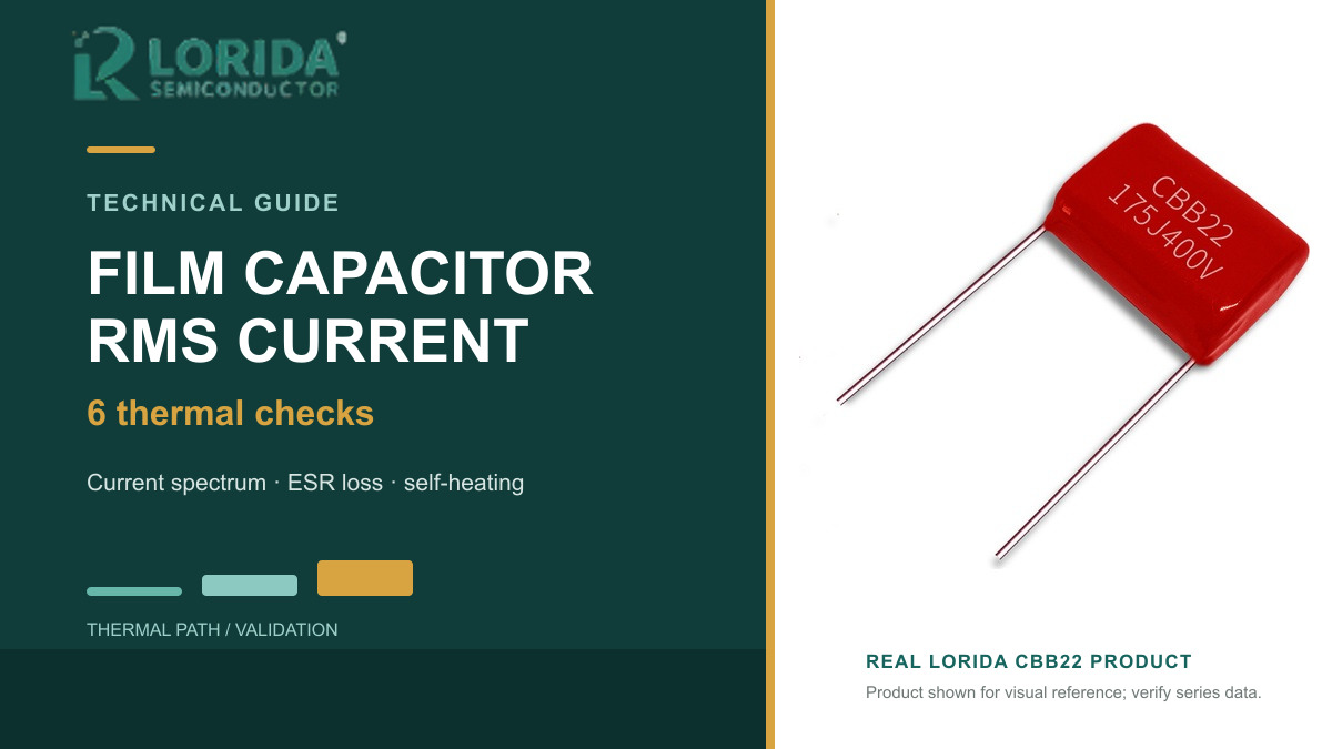
For product-level discussion, review LORIDA's film capacitor range and the CBB22 film capacitor example. For high-power inverter context, also see the DC-link film capacitor selection guide.
Frequently Asked Questions
Can I select a film capacitor from capacitance, voltage and one RMS-current value?
No; one current value is not enough for reliable selection. The same RMS current can produce different heating when frequency content, ESR, dissipation factor, ambient temperature or cooling changes. Send the current spectrum, AC and DC voltage waveforms, switching frequency, duty cycle, enclosure conditions and required life. Then compare those inputs with the exact series' frequency curves, thermal model and hot-spot limit. Finish with temperature and electrical measurements in the real assembly rather than transferring a rating from a different package or manufacturer.
Does lower ESR always mean the capacitor will pass the thermal test?
No; lower ESR reduces one loss term but does not close the full thermal calculation. Dielectric loss, terminal and end-spray current, ambient temperature, thermal resistance, airflow and nearby components can still raise the hot spot. ESR also varies with frequency and temperature. Use the series-specific data at the relevant operating point, calculate both dielectric and resistive loss, and check the permitted temperature rise. A prototype measurement is still required because the enclosure and PCB can change heat removal compared with catalog test conditions.
What should I measure during prototype validation?
Measure current spectrum, voltage waveform, local ambient and case temperature at the defined point. Record probe type and placement, airflow, load mode, stabilization time and measurement uncertainty. Test the worst credible steady-state condition and relevant overload or intermittent modes. After the run, check capacitance, dissipation factor, insulation condition and visible damage according to the supplier's instructions. If the hot spot cannot be measured directly, use the supplier's approved method to infer it from case temperature and thermal data; do not invent a universal offset.
Request a Film Capacitor Thermal Review
Send LORIDA the current spectrum, voltage waveform, ambient and airflow conditions, mechanical drawing, life target and sample quantity. We can use that evidence to discuss a suitable series and validation plan.
Technical Sources
Primary manufacturer documents
TDK Electronics, Film Capacitors - General Technical Information.
TDK Electronics, Thermal Design of Capacitors for Power Electronics.
Last Updated: November 19, 2026


