

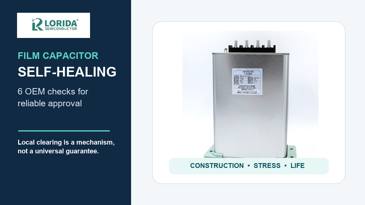
Film capacitor self-healing means a tiny dielectric breakdown can be electrically isolated when the ultra-thin metallization clears around the fault. It is a valuable protection mechanism, but it is not permission to ignore voltage, pulse current, temperature, humidity, or lifetime. OEM approval should therefore verify the exact construction, operating stress, thermal margin, environmental test, and acceptance evidence for the selected series.
Key Takeaways
The decision in one minute
Self-healing is a local clearing event, not a guarantee against every failure mode.
Approve the exact capacitor series against the real voltage waveform, ripple, ambient temperature, cooling, humidity, and required life.
Ask for construction and qualification evidence rather than relying on the words “self-healing.”
Use first-article measurements to close the gap between the datasheet and the assembled equipment.
What does film capacitor self-healing actually mean?
A controlled clearing event around a weak point
In a metallized film capacitor, the electrode is extremely thin. TDK’s general technical guide gives a typical metallization thickness of 20–50 nm. If a weak point breaks down, the local energy vaporizes metallization around that spot and electrically separates it from the healthy electrode area. TDK describes a local plasma temperature of up to 6000 K and says the discharge is quenched after only a few microseconds. The capacitor can continue operating because the affected area is very small relative to the full active area.
Why the word “self-healing” is easy to overread
The mechanism does not reset the component to a factory-new condition. Every event removes a small amount of active electrode area, and repeated or energetic events can produce cumulative capacitance loss, gas generation, pressure, or thermal stress. Whether an event remains benign depends on film system, metallization pattern, segmentation, fault energy, encapsulation, and protection design. For sourcing, “self-healing” is the start of a technical review, not the end of it.
Which six OEM checks matter most?
1–2: construction and electrical stress
First, confirm the dielectric and electrode construction. Ask whether the selected series uses polypropylene, polyester, or another film system; whether it is metallized or film/foil; and whether segmented metallization or a protection device is used. Second, characterize the real electrical stress. Record steady DC or AC voltage, transient overshoot, switching frequency, ripple current, pulse repetition, and discharge path. A label voltage alone cannot describe the energy available at a defect.
3–4: temperature and parasitic inductance
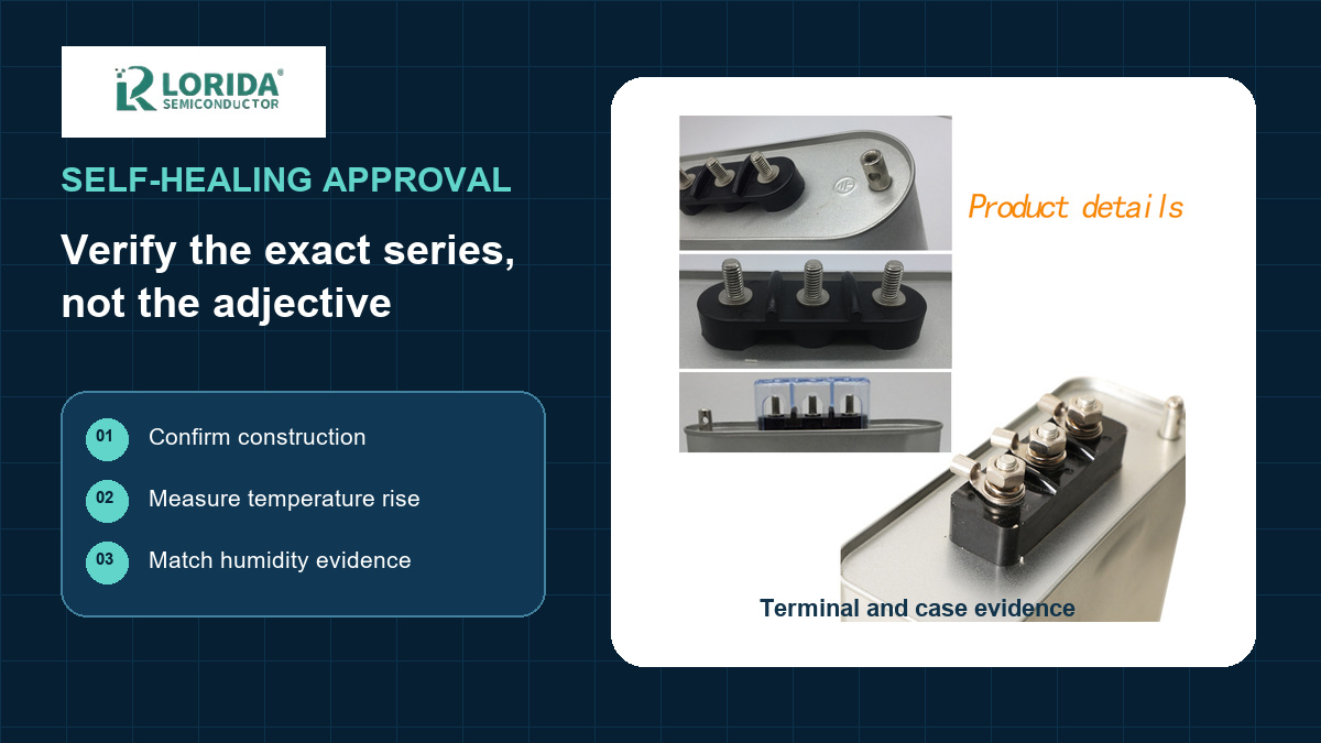
Third, calculate and measure temperature rise. TDK’s general guide lists maximum self-heating examples of 10°C for polypropylene and 15°C for PET/PEN; these are source examples, not universal limits. Use the exact series documentation and verify the hottest installed condition. Fourth, control connection inductance. TDK gives a general rule of thumb of about 1 nH per millimetre of lead plus capacitor length. Busbar geometry and terminal spacing can therefore affect overshoot and fault energy.
5–6: humidity qualification and end-of-life behavior
Fifth, match humidity testing to the application. Insulation resistance generally decreases as humidity rises. A TDK rugged DC-link example uses a THB test of 60°C, 95% RH, rated voltage, and 1000 hours, while special designs are described at 85°C/85% RH/rated voltage/1000 hours. Sixth, define safe end-of-life behavior. Ask what happens after cumulative clearing, which protection feature acts, and what change in capacitance, dissipation factor, insulation resistance, leakage, or case condition causes rejection.
How should an RFQ document self-healing requirements?
Specify evidence, not adjectives
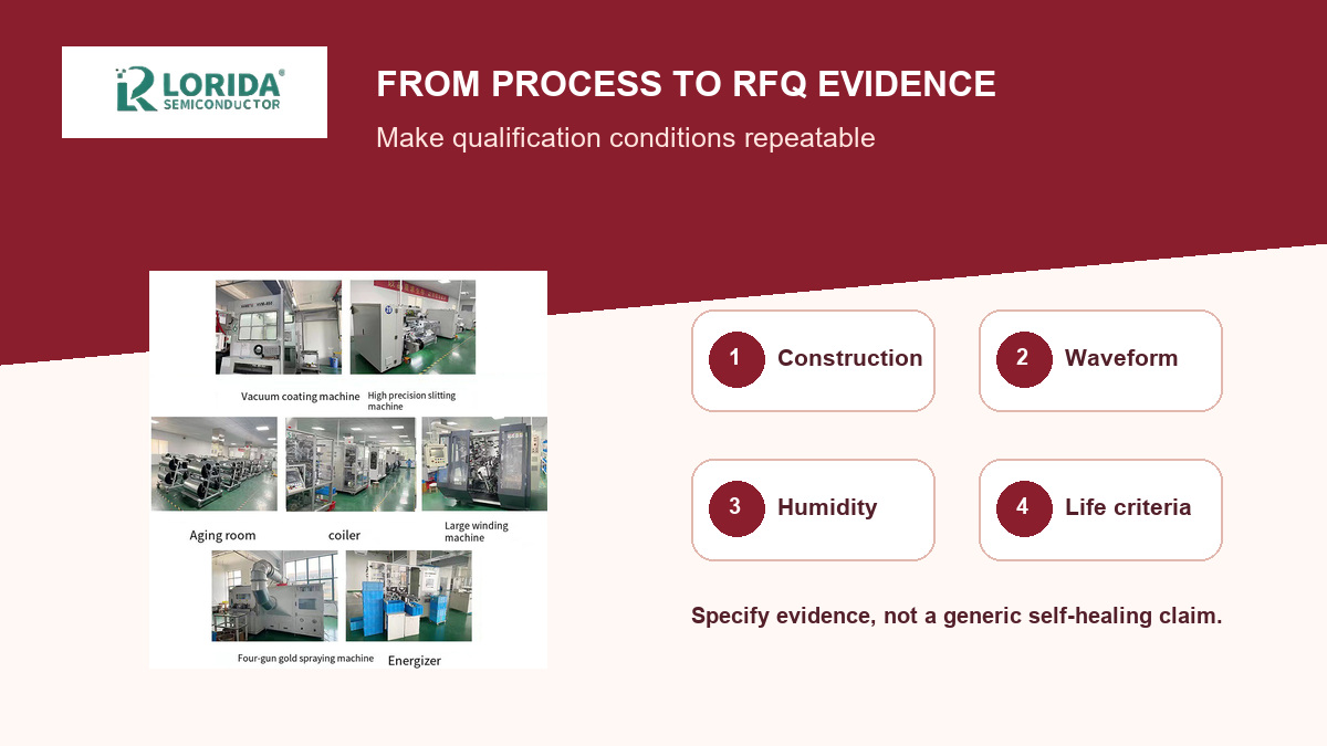
An effective RFQ connects the component to the equipment. Include the circuit function, waveform capture point, maximum normal and abnormal voltage, ripple or pulse current, repetition rate, ambient and hotspot temperature, cooling method, altitude, humidity class, expected duty cycle, life target, mechanical envelope, terminals, and applicable safety standard. Attach the waveform rather than describing it as “high pulse.” For a film capacitor or CBB81 capacitor, request the exact series datasheet and the supplier’s written selection basis.
Use a compact approval table
| Check | Buyer input | Evidence to approve |
|---|---|---|
| Construction | Dielectric, circuit role, failure preference | Exact series construction and protection description |
| Electrical | Waveform, ripple, pulses, abnormal states | Ratings and derating comparison |
| Thermal | Ambient, cooling, nearby heat | Measured hotspot and self-heating margin |
| Environment | Humidity, altitude, contamination | Named qualification method and acceptance limits |
| Lifetime | Duty cycle and required service life | Life model, assumptions, and end-of-life criteria |
What can self-healing not guarantee?
It cannot compensate for a wrong application envelope
A self-healing capacitor can still fail if repetitive clearing exceeds its design capability, ripple heating is excessive, terminals are loose, moisture penetrates the enclosure, or overvoltage lasts too long. A high-energy short circuit, poor creepage, contamination, and unsuitable protection coordination can also dominate the outcome. Self-healing should therefore sit inside a complete design review with fusing, discharge, thermal, insulation, and mechanical checks.
Published endurance figures are series-specific
For perspective, one TDK robust family publishes 50,000 hours at rated voltage and 85°C, while another publishes 95,000 hours at rated voltage and 70°C with self-inductance examples of 11.5–23 nH. These figures demonstrate why the test conditions must travel with the number. They are not interchangeable and are not LORIDA ratings. Apply only the limit and life model documented for the proposed part number.
How should the first article be validated?
Measure the assembled unit
Verify capacitance, dissipation factor, insulation resistance, terminal condition, dimensions, and label traceability before energizing. Then capture the actual voltage and current at the capacitor terminals, not at a remote controller node. Measure the capacitor case temperature after thermal stabilization and compare the result with the supplier’s derating rules. If the application involves switching pulses, combine this review with the film capacitor dV/dt checklist.
Retain evidence for change control
Store the approved datasheet revision, material description, waveform, test setup, ambient conditions, measured temperature rise, sample lot, and acceptance results. Define which material, winding, metallization, case, resin, or production-site changes require notification or requalification. The record makes later failure analysis faster and prevents an apparently equivalent replacement from entering production without a repeatable engineering comparison.
Frequently Asked Questions
Does self-healing mean a film capacitor cannot short-circuit?
No, self-healing does not mean a film capacitor can never short-circuit. It describes the intended clearing of small local dielectric breakdowns in a metallized construction. Severe overvoltage, sustained arcing, contamination, moisture ingress, loose terminals, overheating, or a fault with too much available energy can exceed that mechanism. The equipment still needs appropriate fusing, discharge, insulation coordination, thermal management, and abnormal-condition testing. Ask the supplier how the exact series behaves at end of life and which protective feature is intended to operate before approving it.
Is every metallized polypropylene capacitor self-healing?
Many metallized polypropylene capacitors are designed to self-heal, but the capability is not identical across products. Metallization thickness, pattern, segmentation, film thickness, winding pressure, impregnation, case design, and protection features influence the clearing energy and cumulative behavior. A generic material name therefore cannot replace an exact series review. Confirm the construction in writing, then compare the voltage, pulse, ripple, temperature, humidity, and lifetime limits against the real application. If the proposal changes, repeat the comparison for the new part number.
How do humidity tests relate to self-healing reliability?
Humidity tests show whether a capacitor maintains key electrical properties under sustained moisture and voltage stress. Moisture can reduce insulation resistance and can contribute to corrosion or edge degradation, changing the conditions under which local clearing occurs. The useful question is not whether a product is “humidity resistant,” but which temperature, relative humidity, applied voltage, duration, and acceptance limits were used. For example, TDK publishes a named X2 series test of 1000 hours at 85°C, 85% RH, and 240 V AC with less than 10% capacitance change; that result applies only to that series and test.
What information should I send for capacitor selection?
Send the real electrical, thermal, environmental, mechanical, and lifetime envelope. Include the circuit function, schematic location, capacitance and tolerance, normal and abnormal voltage waveforms, ripple or pulse current, switching frequency, ambient and hotspot temperatures, cooling method, humidity and altitude, duty cycle, life target, dimensions, terminals, mounting, and applicable standard. Photos and oscilloscope captures are often more useful than a generic description. You can send your application requirements to LORIDA for a series-specific review.
Sources and update record
Primary references used
Sources: TDK Film Capacitors General Technical Information; TDK rugged DC-link capacitor technical articles; TDK humidity-resistant X2 announcement; KEMET Film Capacitor Safety. Numerical examples remain attributed to their named manufacturers and do not state LORIDA product ratings.
Last Updated: October 7, 2026


