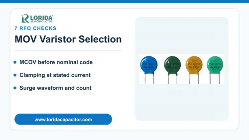
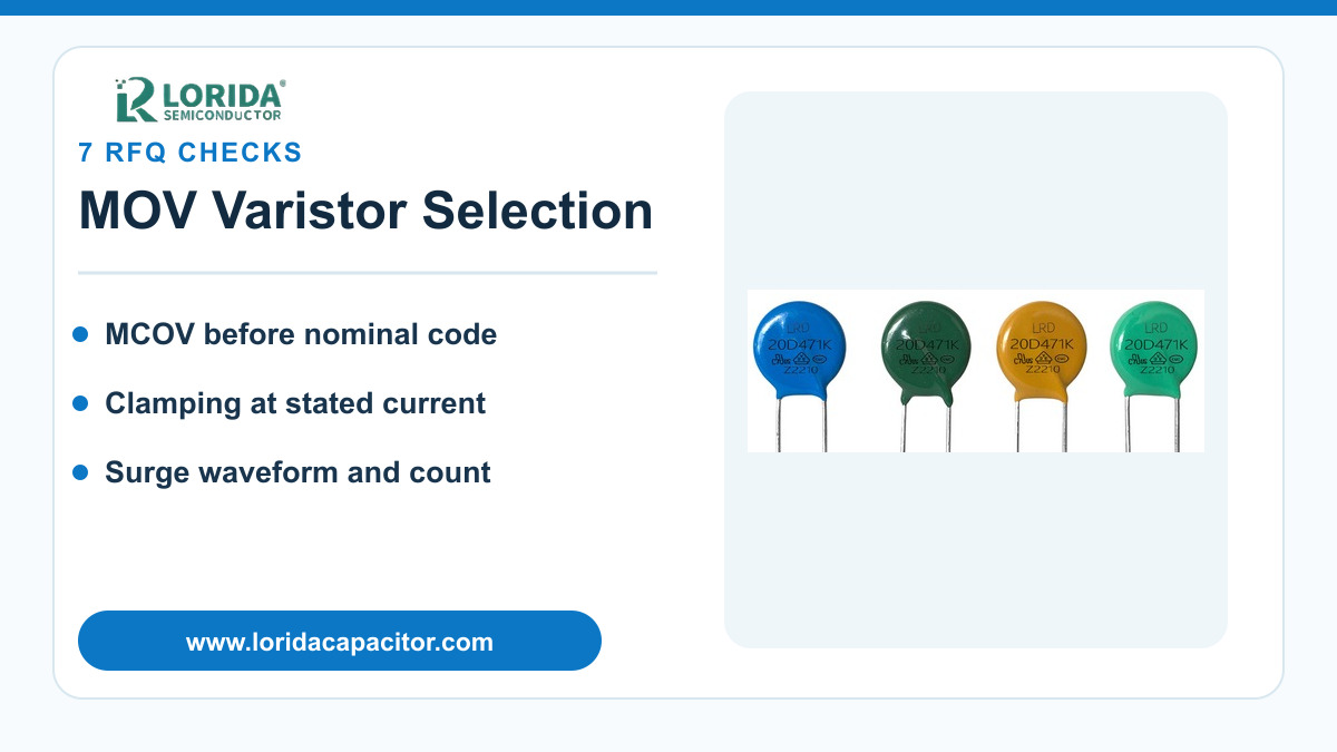
Select an MOV varistor by maximum continuous operating voltage, clamping voltage at a stated current, surge waveform, pulse count, temperature, and mechanical fit—not by the printed voltage code alone. For an RFQ, give the real AC or DC line condition and the expected transient duty so the supplier can compare a specific series safely. The checklist below separates general MOV selection logic from any series-specific rating.
MCOV must cover normal line variation; it is not the same as varistor voltage or clamping voltage.
Surge current and energy ratings only have meaning with the specified waveform, pulse count, and temperature.
Low-inductance placement and sample testing in the final circuit are part of selection, not afterthoughts.
1. Start with the continuous operating voltage
Use MCOV, not the nominal marking, as the first screen
The maximum continuous operating voltage (MCOV) is the voltage the MOV can withstand continuously under the conditions in its datasheet. Record whether the circuit is AC RMS or DC, the nominal value, the permitted high-line condition, and any abnormal overvoltage that may last longer than a transient. A part selected too close to the normal ceiling can conduct leakage current, heat, and age prematurely. A part selected too high may allow an unacceptable let-through voltage.
Do not copy a voltage code from an existing disk without the series datasheet. As an external-series example, the Bourns MOV-20DxxxK sheet spans 11–1100 V RMS and 18–1800 V in nominal varistor voltage across the family; those are family ranges, not LORIDA product claims. Match the exact order code to its row and tolerance before comparing candidates.
2. Separate varistor voltage from clamping voltage
Ask for the test current behind every voltage value
Varistor voltage is commonly measured at a small reference current, while clamping voltage is specified at a much larger surge current. They answer different questions. A buyer who sends only “471K” or “470 V” leaves the protected equipment’s actual voltage stress unresolved. The RFQ should state the maximum voltage the downstream circuit can tolerate and the surge current used for comparison.
The Bourns 20 mm reference series specifies varistor voltage at 1 mA DC and clamping at a class current using an 8/20 µs waveform. Its stated varistor-voltage tolerance is ±10%. These exact test conditions show why a number without its current and tolerance cannot support an engineering substitution.
3. Define the surge waveform and repetition
Peak current and joules need a time shape
Peak current, energy, and pulse life cannot be compared without the waveform. For mains surge protection, an 8/20 µs current impulse is common in component tables, but the end equipment may face a different source impedance, combination wave, or repetitive switching transient. State the expected peak current, waveform, source, number of events, interval between events, and whether simultaneous line conditions are present.
TDK’s SIOV technical information explains that the V/I curves in its data book are measured above 1 mA with the standard 8/20 µs waveform. TDK also warns that operating beyond the type-specific maximum surge current can destroy the component. Use these limits to frame sample tests rather than extrapolating a curve beyond the published region.
4. Check temperature, leakage, and aging
Use the enclosure hot spot, not room temperature
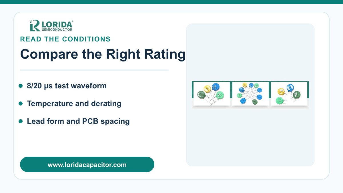
Ambient temperature, heat from adjacent parts, sustained line bias, and surge history all affect MOV stress. Provide the expected temperature at the component location, ventilation, duty cycle, and the required service environment. If the datasheet shows derating, apply it to surge current, energy, or power as specified. A room-temperature single-pulse rating is not automatically valid inside a warm enclosed power supply.
For an external reference point, the Bourns MOV-20DxxxK sheet lists an operating range of −40 to +105 °C and storage from −40 to +125 °C. The same sheet lists 1.00 W maximum rated wattage at 25 °C. These values belong to that Bourns series only, but they illustrate the categories an RFQ should request for the proposed LORIDA candidate.
5. Keep the current path short and low-inductance
Placement changes the voltage seen by the load
An MOV may respond quickly, yet long traces and leads add inductive voltage during a fast current rise. Place the device close to the protected path, minimize loop area, and specify lead length and PCB layout constraints. TDK notes that metal-oxide varistor ceramic responds in the subnanosecond region, while the varistors in its cited data book have response times below 25 ns; it also recommends low-inductance layout for steep surge currents.
The RFQ should therefore include a board drawing or photo, lead spacing, available disk diameter and thickness, maximum installed height, lead form, coating clearance, and any insulation barrier. Mechanical equivalence is part of electrical protection because added connection length can increase let-through voltage.
6. Compare candidates with the same conditions
Normalize the datasheet before choosing a sample
| RFQ field | What to provide | Why it matters |
|---|---|---|
| Continuous voltage | AC RMS or DC, nominal, high line, duration | Sets the MCOV screen and leakage margin |
| Protection limit | Maximum acceptable equipment voltage and test current | Allows clamping comparison at a common point |
| Surge duty | Waveform, peak current, energy, pulse count, interval | Prevents single-pulse ratings being misapplied |
| Thermal condition | Hot-spot temperature, enclosure, adjacent heat | Supports correct derating |
| Mechanical envelope | Disk size, thickness, height, spacing, lead form | Confirms fit and low-inductance placement |
| Validation | Sample quantity, surge test plan, acceptance evidence | Connects the datasheet choice to the final circuit |
Compare only values taken at the same waveform, current, temperature, and pulse count. If two suppliers use different conditions, mark the row as not directly comparable. Review LORIDA’s MOVS varistor category for available product context, then send the exact operating data for candidate matching.
7. Validate the sample in the final circuit
Confirm both protection and post-surge condition
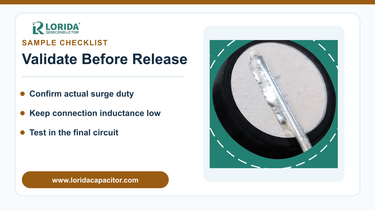
A component-level rating does not replace equipment validation. Test the selected sample with the intended protection topology, fuse or thermal disconnect, PCB layout, enclosure, and representative line conditions. Record peak voltage at the protected node, MOV current, temperature rise, leakage after stress, visible condition, and any change in measured varistor voltage. Define acceptance limits before testing.
TDK’s application information states that its varistor model is valid only inside the specified current range and that simulations for critical applications should be verified with a test circuit. This is a useful purchasing rule: request enough samples for the planned validation, but do not turn a generic simulation into a guaranteed service-life claim.
Frequently Asked Questions
Can I replace an MOV using only the printed code?
No; the printed code alone is not enough for a controlled replacement. The code may indicate a nominal varistor-voltage family, but it does not prove the same MCOV, clamping voltage at the same current, surge-current rating, energy rating, pulse-life curve, disk dimensions, coating system, or lead form. First identify the original manufacturer and full series if possible. Then compare both datasheets under identical test conditions. If the original series is unknown, provide the circuit voltage, protected-node limit, expected surge waveform, temperature, board spacing, and available envelope. Treat the new part as a fresh engineering selection and verify samples in the final circuit.
Is a higher joule rating always a safer choice?
No; a higher joule number does not by itself guarantee better protection or longer life. Energy ratings depend on the waveform, pulse duration, pulse count, temperature, and the manufacturer’s test method. A physically larger MOV may absorb more energy yet also have a clamping behavior that does not meet the protected circuit’s voltage limit. Compare MCOV, clamping voltage at the same current, peak current for the same waveform, repetitive-pulse information, and derating together. The equipment fuse or thermal disconnect and PCB layout also affect the outcome. Use the joule value as one verified row in a normalized comparison, not as the only selection criterion.
Why can two MOVs with the same varistor voltage clamp differently?
They can clamp differently because varistor voltage and high-current clamping voltage describe different parts of the V/I curve. Disk geometry, material formulation, tolerance, lead inductance, and the current used for the clamping test all influence the measured result. Even within one nominal code, the tolerance band means the reference voltage is not one exact value. Compare the maximum clamping voltage at the same surge current and waveform, not just the 1 mA reference voltage. Then check the actual board loop because connection inductance adds voltage during a fast surge. Final-circuit measurement is the reliable way to confirm the protected node stays within its limit.
What should I send with an MOV sample request?
Send the electrical duty, mechanical envelope, environment, and validation target. Include AC RMS or DC operating voltage, high-line condition, acceptable protected-node voltage, surge source and waveform, peak current or energy estimate, expected number and spacing of events, enclosure hot-spot temperature, disk diameter and thickness limits, lead spacing and form, installed height, and any insulation constraints. Add photos or drawings of the board and state the original full part number when available. Explain the sample test and acceptance criteria. This information lets LORIDA compare a candidate against real conditions without inventing a “drop-in” guarantee from a partial marking.
Prepare an MOV varistor RFQ
Send your line voltage, surge waveform, protection limit, temperature, and mechanical envelope for candidate review.
Send your MOV requirementsRelated reading: NTC inrush current limiter selection and the LORIDA product center.
Last Updated: September 9, 2026
Bourns, MOV-20DxxxK Series datasheet: https://www.bourns.com/docs/product-datasheets/mov20d.pdf
TDK Electronics, SIOV metal oxide varistors—general technical information: https://www.tdk-electronics.tdk.com/download/539174/8954d4a78154a9da5c70a7119fa03e86/siov-general.pdf
TDK Electronics, SIOV applications: https://www.tdk-electronics.tdk.com/download/539220/8cd06030e8ddf20bd381c1e8917f0e9c/siov-applications.pdf