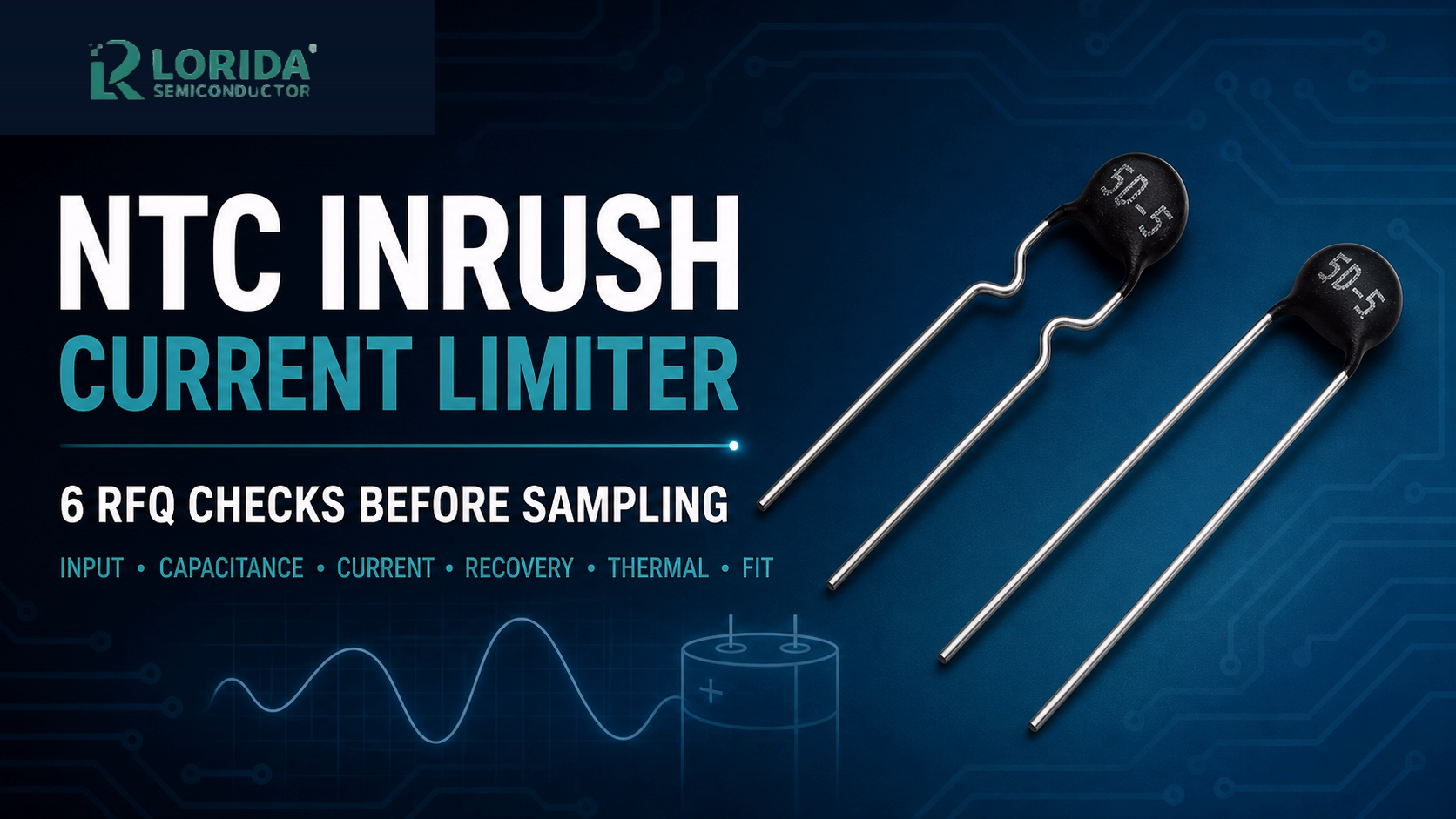
An NTC inrush current limiter should be selected from the real start-up duty, input capacitance, repetition rate, steady current, cooling interval and mechanical envelope—not from its disc diameter or nominal resistance alone. For a LORIDA sample request, provide the complete electrical and thermal context so the proposed part can be checked against its own datasheet and then validated in the finished equipment.
Last Updated: 2026-09-01
Key Takeaways
Buyer checklist
Initial resistance limits the first charging event; it is not the whole selection.
Input capacitance, AC range and repeated restart behaviour need to be stated together.
A hot NTC has a much lower resistance than a cold unit, so a fast restart may have a different inrush profile.
Request the exact proposed part's current, energy, temperature and mounting data before approving a sample.
What an NTC Inrush Current Limiter Does
Start with the cold and hot conditions
An NTC thermistor used as an inrush current limiter begins with a higher resistance. In series with an AC input or DC bus charging path, that resistance reduces the first surge into the rectifier, bulk capacitor or other input load. As the disc heats under current, its resistance falls and the operating voltage loss changes. The important consequence is that one resistance value cannot describe every operating condition. The buyer needs both the cold-start condition and the warmed operating condition, along with the duty cycle that connects them.
Use published values only as evidence models
Manufacturer values are useful when they make the required questions concrete. For example, TDK’s B57236S0200M000 is a 20 ohm NTC inrush-current-limiter example at 25 C with a plus/minus 20% tolerance. Its published test capacitance is 300 uF at 230–240 VAC and 1200 uF at 110–120 VAC, with a 2.8 A maximum-current entry. TDK also states an operating range of -55 to 170 C for that exact part. These are TDK series values, not LORIDA specifications and not a substitute for testing another part.
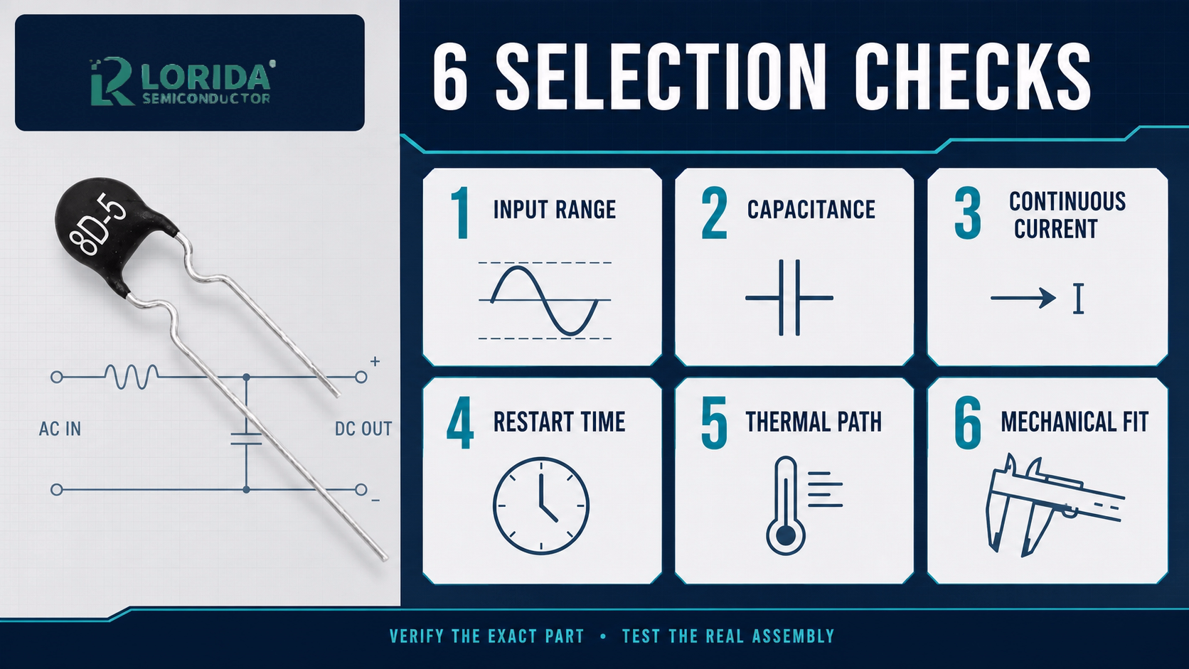
Six RFQ Checks Before Sampling
1. State the input voltage and worst credible line condition
Give the nominal AC or DC input, its tolerance, frequency where relevant, and the highest credible start-up voltage. Include whether the equipment may be connected at a peak of the AC waveform. A limiter that is acceptable at a typical bench supply can see a more demanding charge event at a high line, cold ambient or unusually high bulk-bus voltage. If a bridge rectifier or active PFC sits after the limiter, identify that topology and any controlled start sequence. A useful RFQ does not merely say “110 V” or “230 V”; it defines the expected range and the test condition.
2. Identify the capacitance and load that create the surge
List the total effective input capacitance, including parallel bulk capacitors, and identify whether downstream loads begin drawing current during charging. Do not copy a reference capacitance from an unrelated component. TDK’s cited 20-ohm example uses different published test capacitances at 230–240 VAC and 110–120 VAC, which illustrates why voltage and capacitance must be submitted as a pair. Add pre-charge relays, bypass contacts, discharge resistors and any power-factor-correction timing, because each can change the stress on the NTC.
3. Separate continuous current from the charging pulse
Give normal RMS or DC current, maximum duration, start-up pulse shape, pulse width, number of starts per hour and any fault restart logic. A limiter may survive one cold charge event yet overheat when starts repeat before it cools. TDK’s S236 family datasheet, for example, lists a 2.1 W maximum power at 25 C, about 10 mW/K dissipation factor, about 70 seconds thermal cooling time constant and about 700 mJ/K heat capacity for the cited family. Those figures belong only to that cited family; the lesson is to request equivalent thermal data for the proposed item.
4. Define recovery time and restart behaviour
An NTC that has not cooled returns to service at a different resistance than a cold device. State the shortest off-time, expected brownout pattern, automatic-retry count and whether a technician can cycle mains quickly. This is especially important for chargers, LED drivers, motor controls, UPS inputs and laboratory instruments that may restart after a protective trip. Ask the supplier whether the exact proposed part has a specified recovery or cooling curve, and validate that curve with the real enclosure temperature rather than in open air alone.
5. Check voltage drop and operating temperature in the assembly
After warm-up, a series limiter still dissipates heat and creates a voltage drop. Measure actual disc temperature, nearby capacitor temperature, PCB clearance, insulation distance and airflow under the representative continuous load. Do not assume a larger disc automatically solves the issue; lead spacing, coating, resistance curve, current rating and enclosure temperature still matter. The TDK S236 data-sheet example gives a climatic category of 55/170/21 and a 25 C rating basis, both reminders that ambient and mounting conditions are part of the rating statement. Use the exact proposed part’s limits for acceptance.
6. Confirm the mechanical and sourcing record
Send the required disc diameter, body thickness, lead spacing, lead diameter, lead forming, PCB hole pattern, coating requirement and safety approvals. For comparison only, TDK lists an 11.5 mm maximum body diameter, 5.0 mm maximum thickness, 5.0 mm lead spacing and 0.60 mm plus/minus 0.05 mm lead diameter for one B57236S0200M000 configuration. Do not transfer these dimensions to a LORIDA item. They show why an RFQ must include a drawing and a photograph of the installed part, especially for a replacement.
RFQ Evidence Table
| RFQ item | Evidence to provide | Why it matters |
|---|---|---|
| Input | Voltage range, frequency, topology | Defines worst start condition |
| Charge load | Effective capacitance and pre-charge path | Determines surge energy |
| Current | Continuous current and start frequency | Separates warm loss from pulse stress |
| Thermal duty | Ambient, enclosure and off-time | Checks recovery and temperature |
| Fit | Drawing, lead geometry and clearance | Avoids mechanical mismatch |
| Validation | Measured inrush and disc temperature | Confirms the real assembly |
For related buyer checks, review LORIDA’s NTC thermal resistor product family, the 5D-5 NTC product listing, and the DC-link precharge resistor sizing guide.
How to Validate the First Article
Test the actual start-up sequence
Install the sample on the intended PCB or harness with the planned rectifier, capacitance, bypass components and enclosure. Capture the input current and bulk-bus voltage at cold start, then repeat the test after the shortest permitted off-time. Record ambient temperature, disc temperature, time to steady state and voltage drop under normal load. If a bypass relay is used, record the timing and contact behaviour. Compare all results with the exact part documentation and the equipment safety requirements; a generic NTC example is not an acceptance limit.
Frequently Asked Questions
Can I select an NTC limiter from the printed resistance alone?
No. Printed or nominal resistance is only the starting point for a cold inrush calculation. A defensible selection also needs input voltage range, effective capacitance, expected current, start frequency, shortest off-time and ambient temperature. An NTC changes resistance as it heats, so the same nominal value can behave differently at a cold start, a quick restart and steady operation. Send those conditions with the mechanical drawing and ask for the datasheet of the exact proposed part. Then confirm inrush, voltage drop and disc temperature in the actual equipment.
Why can a quick restart create a different result?
A quick restart can occur before the NTC has cooled back to its cold resistance. That can reduce its surge-limiting effect even though the part looks unchanged. The exact response depends on the part’s resistance-versus-temperature curve, thermal mass, cooling path, ambient temperature and previous load. Treat it as a test condition, not an assumption. State the shortest permitted off-time and automatic-retry sequence in the RFQ, and measure the current waveform after that interval in the finished enclosure under the worst credible ambient condition.
Can I use another manufacturer’s current or capacitance table for a LORIDA part?
No. Another manufacturer’s table can explain what information to ask for, but it does not prove an equivalent rating. Disc formulation, geometry, coating, leads, rating method, ambient condition and test circuit can all differ. For example, this guide cites TDK values only as clearly labelled examples of source-backed parameters. Request the proposed LORIDA part’s own data and application review. If a replacement is involved, provide marking photographs, dimensions, the old datasheet, circuit conditions and measured failures rather than relying on a nominal resistance match.
What should I measure during first-article approval?
Measure cold-start current, bulk-bus charge behaviour, warm restart current, continuous voltage drop, disc temperature, nearby component temperature and time to cool under the defined ambient conditions. Keep the instrument bandwidth, probe location, line voltage and capacitor configuration in the record. Inspect lead stress, coating condition, clearance and any heat impact on adjacent electrolytic capacitors or plastics. Compare the result with the exact supplied part’s documentation and the equipment’s safety criteria. If the result is marginal, change the design only after reviewing the complete electrical and thermal path.
Technical Sources
Documents used
TDK, B57236S0200M000 product information and S236 NTC inrush-current-limiter datasheet.
LORIDA NTC Thermal Resistor category and 5D-5 product listing, used only to verify available product-family context and image origin.