Last Updated: 2026-08-21
A DC-link precharge resistor limits the inrush current that flows while a discharged capacitor bank charges toward the source voltage. A first-pass passive design starts with the DC-bus voltage, total capacitance and permitted precharge time, then checks initial current, pulse energy, repetition rate, resistor voltage capability and the bypass sequence. The continuous wattage printed on a resistor is not enough: in a precharge event, pulse energy and the cooling interval often control the selection.
This guide explains the calculation method, the limits of the simple RC model, the information a buyer should put into an RFQ, and the sample tests needed before production approval. Equations and numerical examples below describe general engineering relationships or published third-party reference designs; they are not LORIDA product ratings.
Why a DC-Link Capacitor Needs Controlled Precharge
The inrush problem starts with stored energy
DC-link capacitors help stabilize a DC bus by absorbing and releasing energy. Eaton describes the DC-link capacitor as a component that maintains steadier DC voltage by smoothing fluctuations created by rectification and power-electronic switching. At startup, however, a discharged capacitor initially behaves like a low-impedance load. Connecting it directly to an energized source can produce a large current limited mainly by source impedance, cable resistance, contact resistance and capacitor ESR.
Texas Instruments explains that high-voltage systems commonly insert a resistor and a controlled switch during precharge. The precharge path charges the DC-link capacitor before the main positive contactor closes. This reduces the voltage difference across the main contactor and helps avoid arcing, contact pitting, fuse stress and cable stress. After the capacitor voltage approaches the source voltage, the controller closes the main path and removes the precharge branch from normal operation.
The energy stored in an ideal capacitor is:
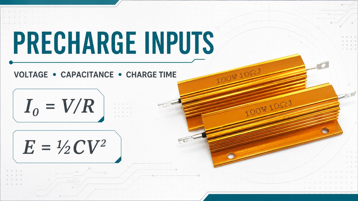
E = 1/2 × C × V²
where E is energy in joules, C is capacitance in farads and V is capacitor voltage in volts. The squared-voltage term matters. If capacitance stays constant while voltage doubles, stored energy becomes four times larger. That is why a resistor that survives a low-voltage prototype may be unsuitable for a higher-voltage platform even when the target precharge time appears similar.
Passive and active precharge are different architectures
A passive precharge circuit places resistance in series with the DC-link capacitor, creating an RC charging curve. TI describes this capacitor voltage as an exponentially rising function. Passive precharge is conceptually simple and may be appropriate when the event frequency, energy and required charge time fit a resistor-based design.
Active precharge uses controlled semiconductor switching and energy conversion to regulate charge current. TI notes that an active buck-type precharge can charge the capacitor with approximately constant current, creating a more linear voltage rise. Active approaches may reduce the size or stress of the passive resistor in demanding systems, but they add control, switching, protection and validation requirements.
The resistor calculation in this article applies to a passive RC precharge path. It should not be copied into an active topology without reviewing the controller supplier's design method.
Check 1: Define the Real Electrical Requirements
Record maximum voltage, not only the nominal label
Start with the maximum voltage that can appear across the precharge path. Include the source's upper tolerance, battery state of charge where relevant, regenerative conditions, charger output tolerance and credible transient states. Do not use the motor nameplate voltage as a substitute for measured or specified DC-bus voltage.
The RFQ should distinguish at least four values:
nominal source or bus voltage;
maximum continuous source voltage;
maximum credible transient voltage;
voltage expected across the resistor at the start of precharge.
These values affect resistance, initial current, pulse power, creepage and clearance, resistor construction, insulation, switching-device stress and series/parallel arrangements. The supplier also needs to know whether the assembly is floating or chassis referenced.
Use total effective DC-link capacitance
Use the total capacitance charged by the precharge branch. If several capacitors are connected in parallel, their capacitances add. If the bank contains series-connected capacitors, the equivalent capacitance is lower than the individual value and voltage-sharing components may also affect the circuit.
Include capacitance tolerance and any additional capacitive loads downstream of the main contactor. A design calculated from the nominal bank value alone may charge more slowly if actual capacitance is at its upper tolerance. Conversely, a lower actual capacitance can raise the achieved voltage more quickly, which may change the controller's timing assumptions.
For replacements, provide the capacitor-bank drawing, original capacitor data, measured capacitance if service history matters, and the reason for the change. Do not assume that a replacement capacitor with the same headline capacitance creates the same ESR, leakage, temperature behavior or mechanical connection.
Check 2: Calculate Resistance from the Required Charge Time
Use the RC charging equation
For an ideal source Vₛ, series resistance R and capacitance C, capacitor voltage during charging is:
V꜀(t) = Vₛ × (1 − e^(−t/RC))
Rearranging for resistance gives:
R = −t / [C × ln(1 − V꜀/Vₛ)]
This equation is more useful than selecting a convenient number of time constants without defining the target voltage. At one time constant, the capacitor reaches about 63.2% of the final voltage. At three time constants it reaches about 95.0%. At five time constants it reaches about 99.3% in the ideal model. TI's 2024 passive-precharge reference design uses five time constants as its example completion criterion, while also noting that some systems may require a longer interval to meet contactor voltage-drop requirements.
Suppose a controller requires the capacitor to reach 90% of the source voltage in a specified time. The required interval is about 2.303RC, not 5RC. The correct threshold must come from the system control and contactor requirements—not from a generic online calculator.
Check initial current and source limits
At the instant an ideal discharged capacitor is connected, initial current is approximately:
I₀ = Vₛ / R
This is the highest current in the ideal passive RC event. It decays exponentially as capacitor voltage rises. Check it against the resistor's pulse-current capability, precharge switch or contactor rating, fuse behavior, cable limits, connector limits and source current capability.
The initial resistor power is:
P₀ = Vₛ² / R
This can be a very large number, but it exists only briefly. TI specifically warns against choosing a precharge resistor by treating that initial peak as a continuous-power requirement. The relevant comparison is the manufacturer's pulse-energy or overload curve for the actual pulse duration, waveform, starting temperature and cooling condition.
Check 3: Size the Resistor for Pulse Energy, Not Wattage Alone
Relate capacitor energy to resistor stress
In an ideal RC charge from zero volts, the source supplies C × V² joules. Half becomes stored capacitor energy, 1/2CV², and half is dissipated in the series resistance. Real systems add losses in wiring, switching devices, ESR and auxiliary components, so the engineering review should use the actual circuit rather than assume every joule lands in one component. Still, 1/2CV² is a useful first-pass estimate of the resistor's pulse-energy burden for a full charge event.
TI's high-voltage passive-precharge reference design provides a concrete, source-specific example: its published requirements use an 800 V system, 2 mF DC-link capacitance and a 0.5 s precharge time. Using a five-time-constant criterion, the design calculates 50 Ω and approximately 1,000 J of capacitor energy. Those numbers belong to the TI reference design; they are not a universal recommendation and are not LORIDA specifications.
This example shows why a catalogue's continuous wattage column cannot answer the question by itself. The resistor needs documented capability for the required energy, pulse shape, pulse length, starting temperature and number of cycles.
Check repetition rate and incomplete cooling
One startup per day and repeated test-bench cycling are different thermal duties. Ask for:
pulses per hour and maximum consecutive pulses;
minimum time between attempts;
whether failed precharge can trigger an automatic retry;
ambient temperature at the resistor;
enclosure airflow and mounting surface;
worst-case starting temperature after normal operation;
required service life or total event count.
Average power over many identical events can be estimated by multiplying energy per event by events per second, but this average does not replace the pulse-overload check. A resistor can meet average wattage and still suffer excessive element temperature during each pulse. Conversely, a component with a modest continuous rating may tolerate a high short-duration pulse when its manufacturer provides a suitable overload curve and the recovery interval is adequate.
Check 4: Verify Voltage, Construction and Failure Behavior
Resistance value is only one electrical rating
The resistor must withstand the voltage applied across its element and insulation system. For a high-voltage bank, a single part may exceed its working-voltage rating even if its resistance and pulse-energy numbers look acceptable. A series string can divide voltage and energy, but tolerance, layout, insulation, parasitic capacitance and failure behavior need engineering review.
Ask the supplier to identify which values are guaranteed in the applicable datasheet or project specification:
| RFQ item | Why it matters | Evidence to request |
|---|---|---|
| Resistance and tolerance | Sets initial current and RC time | Datasheet limit and inspection method |
| Working/overload voltage | Prevents element or insulation overstress | Voltage-rating definition and test condition |
| Pulse energy vs. duration | Determines single-event survival | Manufacturer pulse curve or qualified project data |
| Repetition and cooling | Determines temperature accumulation | Thermal model, derating rule or test plan |
| Temperature coefficient | Changes resistance with temperature | TCR specification |
| Insulation and dielectric strength | Supports high-voltage integration | Test voltage, duration and acceptance criterion |
| Mechanical dimensions and terminals | Controls fit, connection stress and clearance | Controlled drawing |
| Traceability | Supports change and failure analysis | Lot/date code and inspection records |
Avoid comparing a guaranteed limit from one supplier with a typical curve from another. Ask both suppliers to respond to the same waveform, ambient condition and acceptance criteria.
Define safe failure detection and bypass logic
The resistor is one part of a sequence that includes sensing, switching and fault logic. The controller should confirm that DC-link voltage rises as expected before closing the main contactor. An open resistor, welded precharge contactor, shorted semiconductor, wrong resistance, discharged source or unexpected load can all alter the voltage curve.
Define the maximum allowed precharge time, minimum required capacitor voltage, permitted voltage difference across the main contactor and retry behavior. Unlimited automatic retries can create a thermal duty far beyond the resistor's nominal startup cycle. Fault handling should place the system in a safe state and prevent repeated pulses until the cause is understood.
High-voltage commissioning and discharge procedures must be performed by qualified personnel following the equipment's safety requirements. A precharge resistor does not make an energized DC link safe to touch, and it is not automatically a discharge resistor after shutdown.
Check 5: Send a Complete RFQ and Validate Samples
RFQ checklist for a precharge resistor
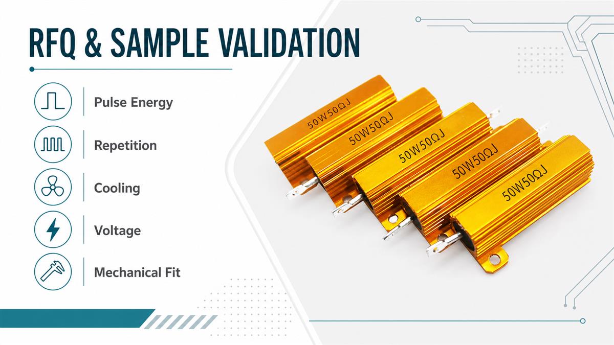
A supplier can respond more reliably when the RFQ includes the complete operating profile:
system application and circuit diagram;
nominal and maximum source voltage;
total DC-link capacitance and tolerance;
initial capacitor voltage before precharge;
target capacitor voltage and allowed precharge time;
calculated resistance and acceptable tolerance;
initial current, peak power and pulse-energy calculation;
normal event frequency, retry logic and worst-case pulse sequence;
ambient temperature, airflow, enclosure and mounting surface;
maximum dimensions, terminal style, cable or busbar arrangement;
insulation, working-voltage and dielectric-test requirements;
sample quantity, annual demand and required documentation.
Include the original calculation sheet rather than only the chosen resistance. This lets the supplier check whether the proposed construction matches the real waveform and duty. If the design is a replacement, attach clear photos, markings, dimensions, the original specification and the failure or sourcing reason.
Sample validation plan
Before production approval, verify the resistor in the intended assembly and under a controlled, representative sequence. Measure and record:
source voltage and capacitor voltage versus time;
initial current and current decay;
actual precharge completion threshold;
resistor temperature before and after repeated events;
contactor or switch timing;
voltage difference when the main contactor closes;
resistance before and after the test;
insulation, terminals, mounting and visible condition.
Test the worst credible automatic-retry sequence, not only one cold start. Confirm that the controller detects slow charge, no charge and unexpected voltage rise. Any change to capacitance, source voltage, charge time, enclosure temperature, mounting or retry logic should trigger a new technical review.
LORIDA buyers can send the DC-bus voltage, capacitor-bank value, required precharge time, pulse sequence, mounting envelope and expected quantity for a resistor model-matching discussion. Buyers may also review our gold aluminum housed resistor selection guide, VFD braking resistor RFQ guide, and DC-link film capacitor selection guide. Final approval must rely on the exact supplied specification and validation in the customer's system.
Key Takeaways
Five decisions that control the design
Calculate the resistance from the required capacitor-voltage threshold and time, not from a generic rule alone.
Check I₀ = V/R against the complete precharge path.
Check pulse energy using the real capacitance and maximum voltage; do not select by continuous wattage alone.
Include repetition, automatic retries, starting temperature, cooling and voltage capability.
Approve the sample only after measuring the actual voltage, current, timing and temperature in the intended assembly.
Frequently Asked Questions
How do I calculate a DC-link precharge resistor?
Use the RC charging relationship and begin with the maximum source voltage, total effective capacitance, required charge time and target capacitor-voltage percentage. Solve R = −t/[C ln(1 − V꜀/Vₛ)], then calculate initial current with I₀ = Vₛ/R. After that, verify pulse energy, resistor working voltage, switch and fuse current, repetition rate, starting temperature and automatic retries. The calculated resistance is only a first-pass value; the selected component must have manufacturer data or qualified test evidence for the actual pulse duration and thermal duty.
Why can’t I select the resistor from its continuous wattage?
Precharge is normally a short, decaying pulse rather than a steady load. Initial power can be very high, but it falls as the capacitor charges. A continuous wattage rating does not describe how much energy the resistive element and housing can absorb during that pulse. Use the supplier's pulse-overload or energy curve for the required duration, starting temperature and repetition rate. Also check cooling between attempts. A resistor may satisfy average power yet overheat locally during each pulse, especially when the controller permits rapid automatic retries.
How much energy must the precharge resistor absorb?
For an ideal full charge from zero volts through a series resistor, a useful first-pass estimate is the capacitor's stored energy, E = 1/2CV². Real circuits divide losses among the resistor, capacitor ESR, wiring and switching elements, so simulation or measurement may be needed for final allocation. Use maximum credible voltage and upper capacitance tolerance because energy scales linearly with capacitance and with the square of voltage. Then compare the waveform with the resistor manufacturer's specified pulse-energy capability rather than treating the estimate as a guaranteed part rating.
When is precharge complete?
Precharge is complete when the system reaches the voltage threshold and timing conditions required for safe main-path closure—not merely when a timer expires. In an ideal RC circuit, one time constant reaches about 63.2% of final voltage, three reach about 95.0%, and five reach about 99.3%. The actual threshold should account for contactor voltage-drop limits, measurement accuracy, source variation and downstream load. The controller should detect abnormal slow charge or no charge and enter a safe fault state instead of repeatedly pulsing the resistor without limit.
Can the same resistor also discharge the DC-link capacitor?
Not automatically. Precharge and discharge have different switching states, timing, safety objectives and thermal profiles. A precharge resistor may be disconnected after startup and therefore provide no shutdown discharge path. A dedicated discharge circuit may be required to reduce the bus to a defined safe voltage within a specified time. If one component is intended to perform both functions, calculate and validate both duties, including continuous or repeated dissipation, control failure modes, insulation and the interaction between precharge, normal operation and shutdown.