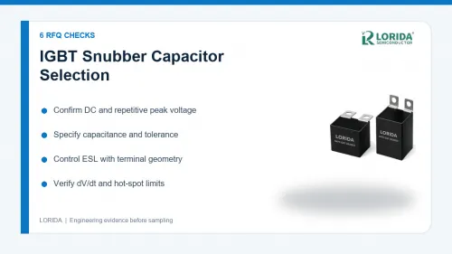
An IGBT snubber capacitor should be selected by voltage waveform, capacitance, repetitive peak current, dV/dt, stray inductance and hot-spot temperature—not by capacitance alone. LORIDA's published IGBT snubber range includes MKPH and MKPD families from 1000 VDC to 2000 VDC, with category-listed capacitance windows from 0.01 µF to 4.5 µF depending on series and voltage class. These are catalogue ranges, not a substitute for matching an exact part to the switch waveform. This guide gives buyers a six-item RFQ structure and separates LORIDA catalogue facts from third-party engineering examples.
Last Updated: 2026-09-07
Need an RFQ-ready part shortlist? Send your DC bus, repetitive peak voltage, capacitance, dV/dt, peak current, switching frequency, ambient temperature and terminal drawing. LORIDA can review candidate MKPH/MKPD options against the information provided.
Key Takeaways
What must be fixed before a sample is ordered
Send the measured or simulated switch-node waveform, including repetitive peak voltage.
Specify capacitance, tolerance, dV/dt, peak current and repetition frequency together.
Treat terminal geometry and mounting distance as electrical parameters because they affect loop inductance.
Ask the supplier to identify the exact datasheet limits used for voltage, current and temperature checks.
What an IGBT snubber capacitor actually controls
Voltage overshoot and commutation-loop energy
A snubber capacitor is placed close to a switching device to absorb high-frequency commutation energy and reduce voltage overshoot. The required capacitance cannot be copied from another converter because loop inductance, switching speed, current and layout change the transient. TDK describes its B3265*S models as film capacitors for DC applications and IGBT-mounting snubbering, and warns that model accuracy is expected below the first resonant frequency. That statement matters in procurement: a linear model is useful for screening, but the final design still needs waveform validation on the target assembly.
Why ESL and terminal geometry belong in the RFQ
Lead and busbar inductance reduce the ability of a capacitor to react to a fast edge. TDK's snubber-cap finder therefore filters not only by rated voltage and capacitance but also by terminal style and terminal drawings. As a separate technology example, TDK reports 3 nH ESL for a 5.7 × 5 × 1.4 mm CeraLink device intended for fast-switching semiconductor snubbers. That figure is not a LORIDA specification; it demonstrates why the mounting loop must be documented rather than assumed.
Six RFQ checks for an IGBT snubber capacitor
Use one evidence package for electrical and mechanical duty
| RFQ check | Evidence to provide | Supplier response to request |
|---|---|---|
| 1. Voltage | DC bus, repetitive peak and abnormal transient | Rated and permissible peak limits for the exact part |
| 2. Capacitance | Target value and tolerance | Value available at the selected voltage class |
| 3. Pulse duty | dV/dt, peak current, pulse width, frequency | Datasheet pulse-current calculation and margin |
| 4. Thermal duty | Ambient, cooling, nearby heat sources | Hot-spot method and temperature limit |
| 5. Layout | IGBT terminals, busbar drawing, loop distance | Terminal drawing and mounting recommendation |
| 6. Validation | Test points and worst-case operating modes | Sample plan and acceptance criteria |
Read catalogue ranges without turning them into guarantees
LORIDA's public category lists MKPH choices at 1000, 1200, 1600 and 2000 VDC. The listed MKPH capacitance windows are 0.068–0.82 µF at 1000 VDC, 0.033–0.68 µF at 1200 VDC, 0.022–0.82 µF at 1600 VDC and 0.01–0.56 µF at 2000 VDC. MKPD listings extend to 4.5 µF at 1200 VDC, 2.2 µF at 1600/1700 VDC and 0.82 µF at 2000 VDC. Buyers should request the exact part drawing and datasheet because the category page does not establish every pulse, thermal or dimensional limit.
How to validate the first sample
Measure the condition that can damage the switch
Test the highest bus voltage, highest load current and fastest switching condition that the product can encounter. Capture switch-node overshoot with a measurement setup whose loop is short enough not to create a false spike. Compare both the voltage peak and ringing pattern before and after the proposed snubber. Record capacitor case temperature after thermal stabilization, and repeat the check at the warmest credible ambient. KEMET's pulse-and-snubber selector shows why exact series matter: its R75 family is listed up to 2000 VDC and a 105 °C hot-spot limit, while R75H is listed to 125 °C. These are third-party examples, not interchangeable ratings.
Keep the approval tied to an exact construction
A change in dielectric construction, internal connection, terminal spacing or case size can change ESR, ESL, current capability and thermal behavior. The sample approval should therefore identify manufacturer, series, part number, revision and drawing. If an alternative is proposed later, repeat the waveform and temperature evidence instead of approving it from capacitance and voltage labels alone. For related converter procurement, see LORIDA's IGBT snubber capacitor range, DC-link film capacitor guide, and product center.
Frequently Asked Questions
Can I select a snubber capacitor from DC voltage and capacitance only?
No; voltage and capacitance are necessary but not sufficient. The switch waveform also creates repetitive peak current and dV/dt stress, while the physical loop adds inductance that can prevent the capacitor from controlling the fastest part of the transient. Send the supplier the measured or simulated overshoot, repetition frequency, pulse width, ambient temperature and terminal layout. Ask for the exact part's pulse-current, dV/dt, hot-spot and mechanical limits. A catalogue range can identify candidates, but the final choice should be verified on the real power stage at worst-case voltage, current and temperature.
Should the snubber capacitor be mounted close to the IGBT?
Yes; the snubber loop should normally be kept as short and low-inductance as the assembly permits. Extra lead, trace and busbar length adds stray inductance, so a capacitor with a suitable nominal value may still respond too slowly to the switching edge. Provide an IGBT terminal drawing, busbar stack-up, hole spacing and proposed capacitor position with the RFQ. During validation, use the same mechanical layout intended for production. A bench test with long temporary leads can give a misleading result because the temporary loop is electrically different from the final assembly.
Is a higher voltage rating always a safe substitute?
Not automatically; a higher voltage label does not prove equivalent pulse or layout performance. Moving to another voltage class can change capacitance availability, case size, terminal geometry and internal construction. Those changes can affect ESL, ESR, current capability and mounting clearance. Re-run the supplier's selection calculation with the exact candidate and confirm that it fits the busbar and thermal envelope. If the proposed substitute changes the case or terminal arrangement, repeat the switch-node waveform measurement and case-temperature check before approval.
What should be included in sample acceptance criteria?
Acceptance criteria should cover the electrical waveform, temperature and physical fit of the exact sample. Record maximum overshoot, ringing behavior, capacitor case temperature, ambient temperature, operating mode and test duration. Confirm terminal alignment, creepage and clearance, fastening method and interference with nearby parts. The report should identify the converter revision, IGBT module, gate-drive condition, capacitor part number and measurement setup. Keep oscilloscope captures and photographs with the approval record so later production changes can be compared against the same baseline.
What to include in the supplier comparison
Normalize every quotation to the same operating point
Compare quotations only after each supplier has answered the same electrical, thermal and mechanical questions. Record rated voltage, permissible repetitive peak voltage, capacitance tolerance, dV/dt limit, peak-current method, dissipation data, terminal drawing, case dimensions and the declared hot-spot limit. If one response gives only a marketing description, mark those fields as missing instead of treating silence as compliance. Ask whether quoted limits assume a particular frequency, waveform, cooling condition or service life. This normalized comparison prevents a low-price candidate with incomplete evidence from appearing equivalent to a fully documented candidate.
Freeze the evidence used for approval
Attach the exact datasheet revision, drawing, quotation and test report to the approved part number. Photographs should show the marking and terminal configuration of the tested sample. If production later changes the terminal, winding construction, resin, case or supplier part number, route the change through engineering review. The aim is not to reject every change; it is to make sure the waveform and temperature evidence still applies to the delivered construction.
Ready to compare a candidate? Attach the six RFQ inputs and identify the IGBT module or busbar drawing. A complete data package helps the supplier answer with an exact series, drawing and validation plan instead of a generic voltage-and-capacitance match.
Sources
Verified references used for exact data
LORIDA IGBT Snubber Capacitor category: https://www.loridacapacitor.com/igbt-snubber-capacitor/
TDK Snubber Cap Finder: https://www.tdk-electronics.tdk.com/en/1116212/design-support/design-tools/film-capacitors/snubber-cap-finder
TDK B3265*S model library notes: https://www.tdk-electronics.tdk.com/en/2970296/design-support/design-tools/film-capacitors/model-libraries/film-capacitors-readme-and-history/3062630
KEMET Pulse & Snubbers product selection: https://www.kemet.com/content/dam/kemet/lightning/documents/ec-content/KEMET_F_R76_PB_X_X-2.pdf