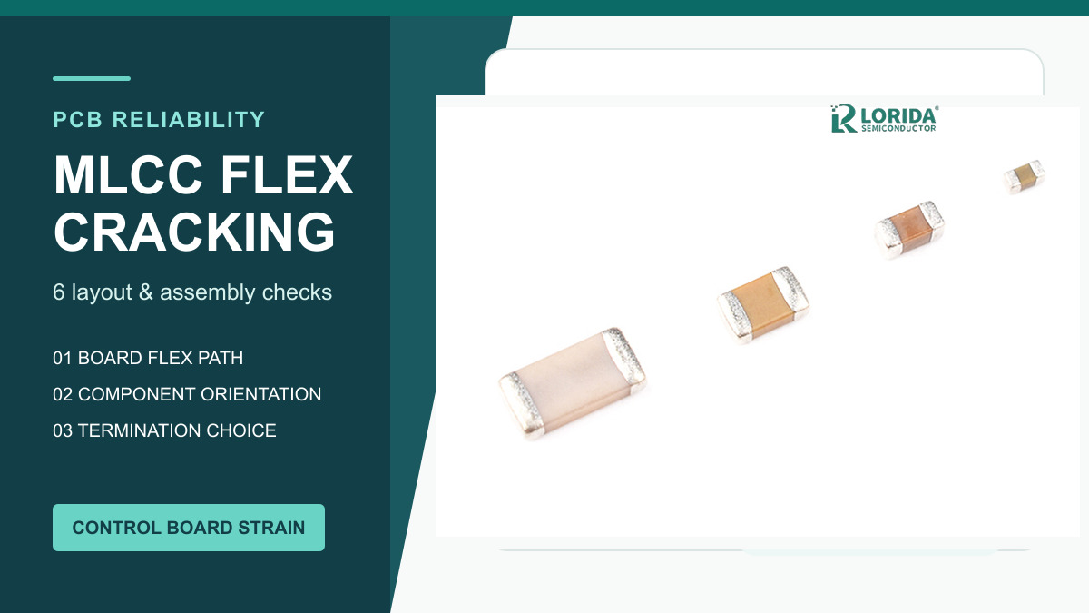
Prevent MLCC flex cracking by controlling board strain, component position, orientation, solder geometry, handling and termination design. A chip capacitor can pass incoming inspection and still crack after placement, depaneling, connector insertion or enclosure assembly. The correct response is a PCB-and-process review, not a capacitance-only replacement.
Key Takeaways
Flex cracks usually originate near the mounted-side termination where board strain concentrates.
External inspection can miss a crack; electrical failure may be delayed until moisture reaches opposing electrodes.
Keep MLCCs away from board edges, score lines, connectors and screw loads whenever the layout permits.
Flexible termination reduces risk but does not replace process control.
Qualify the exact case size, land pattern, board thickness and assembly sequence.
What MLCC flex cracking means
Mechanical strain can become an electrical fault
KEMET explains that excessive PCB strain can stress the rigid ceramic body, producing a crack that may later become a low-insulation-resistance or short-circuit path. The failure is not always immediate: humidity or other conductive contamination can enter the crack and bridge electrodes of opposite polarity. TDK describes the common signature as a crack beginning near the mounted-side termination and travelling upward at about 45 degrees. Preserve the component orientation before cross-sectioning because the crack direction is part of the evidence.
Use published tests as examples, not universal limits
TDK reports a controlled 10 mm substrate-bend example in which standard-terminal parts showed a 100% body-crack occurrence rate while resin-electrode parts showed 0%. The same guide reports no cracks after 10,000 drop cycles for its cited soft-termination example and labels that result as not guaranteed. These values demonstrate a mechanism; they do not authorize a 10 mm production limit for another series, board or package.
Six PCB and assembly checks
1. Map every board-flex source
List depaneling, press-fit connectors, cable insertion, test fixtures, screw tightening, heat-sink fastening and enclosure closure in process order. Mark where the PCB is supported and where force is applied. KEMET identifies connectors and locations near the board edge or depaneling score line as high-risk areas. Measure strain during the actual operation rather than judging risk from a stationary board. Record board thickness, panel geometry, support spacing, tool condition and force direction with the result.
2. Review component position and orientation
Move the MLCC away from score lines, corners, mounting holes and connector load paths where practical. KEMET recommends considering an orientation parallel to the board edge near depaneling zones to reduce flex-crack risk. The correct choice still depends on the local strain field, so confirm it on the real panel. Larger bodies generally intercept more differential board movement; do not approve a package change only because its capacitance and voltage match.
3. Check land pattern and solder volume
Compare copper pads, solder-mask openings and paste apertures with the exact supplier recommendation. Excess solder can raise the termination and transfer more bending stress into the ceramic, while severe imbalance can rotate or lift the part. TDK's solder-crack guide publishes a 2 mm board-flex simulation for a 3225-size example, showing why package, solder joint and terminal structure must be evaluated together. Photograph both joints and section suspect samples before changing the stencil.
4. Control depaneling and manual handling
Support the panel close to the cut, minimize unsupported span and avoid twisting a finished board from one corner. Review router, saw or break-off tooling for wear and alignment. Hand soldering, rework and probe contact add separate thermal or mechanical loads, so record them rather than combining all damage under "board flex." A crack found after final assembly may have originated earlier and propagated during later operations.
5. Consider flexible termination where risk remains
KEMET states that its flexible-termination MLCCs provide up to 5 mm capability for EIA 0402 through 1210 sizes and 3 mm for larger case sizes under the cited test basis. TDK's low-resistance soft-termination example places resin on the board-mounted side and reports ESR at self-resonance approximately 60% lower than its conventional soft-termination comparison. These are supplier-specific examples. Request the exact series datasheet, board-flex method, electrical trade-offs and ordering code before substitution.
6. Validate the finished assembly
Qualification should reproduce the worst credible panel separation, connector insertion, fastening, vibration, drop and temperature sequence. Measure insulation resistance and other relevant electrical characteristics before and after the mechanical steps, then retain cross-sections for failures. Do not rely on capacitance alone. The acceptance plan should name sample quantity, case size, board revision, strain location, environmental conditioning and failure criteria.
Procurement comparison table
Separate design choices from evidence
| Decision | Evidence to request | Risk if omitted |
|---|---|---|
| Standard termination | Approved land pattern and board-flex limit | Ceramic crack under local strain |
| Flexible termination | Exact construction, test method and ESR data | Assuming all soft terminations are equal |
| Case-size change | Capacitance, voltage, bias, thermal and flex review | Mechanical gain with electrical loss |
| PCB layout change | Strain map, panel drawing and assembly sequence | Moving the part into another load path |
How to write the MLCC corrective RFQ
Send the board and process context
Provide the exact capacitance, tolerance, rated voltage, dielectric, case size and current ordering code. Add PCB thickness, copper stack, land pattern, solder paste, component orientation, distance from board edge or score line, depaneling method, connector and screw locations, operating environment and failure evidence. Link the requirement to the LORIDA MLCC range, compare electrical effects with the MLCC DC-bias guide, and send LORIDA the board and duty record for part-number review. Do not request "flex proof" without defining the test.
Frequently asked questions
Can a flex-cracked MLCC still measure the correct capacitance?
Yes, a flex-cracked MLCC may initially measure near its expected capacitance. The crack may not yet interrupt enough electrodes to shift capacitance substantially, and it may not create a conductive path until moisture or contamination enters. That is why a handheld capacitance reading cannot clear a suspect part. Preserve the board, document orientation and process history, measure insulation behavior with the applicable method, and use controlled cross-sectioning or failure analysis when the consequence justifies it.
Does flexible termination eliminate board-flex failures?
No, flexible termination reduces transferred stress but does not eliminate the need to control PCB strain. Supplier test results depend on case size, termination structure, board, land pattern and method. A soft layer can absorb deformation or act as a mechanical fuse, yet excessive bending, poor depaneling or connector force can still damage the assembly. Qualify the exact ordering code on the real board and include electrical trade-offs such as ESR, impedance and DC-bias performance.
Where should MLCCs be placed relative to a panel edge?
Place MLCCs outside the dominant depaneling and connector strain path whenever the design permits. There is no universal safe distance that applies to every board thickness, score geometry, router process and package. Use the panel drawing and strain measurement to locate high-risk zones. Review orientation as well as distance, support the panel near the cut, and repeat measurement after tooling, board or enclosure changes. Record the approved condition in the manufacturing plan.
Primary sources
Manufacturer guidance used for the exact examples
TDK: What does a flex crack look like?
Murata: MLCC cracking causes and preventive guidance.
Last Updated: November 13, 2026. Manufacturer test values are cited examples, not LORIDA-wide specifications. Verify the exact part datasheet and the applicable equipment requirements before approval.