Buyer guide - NTC inrush current limiter selection
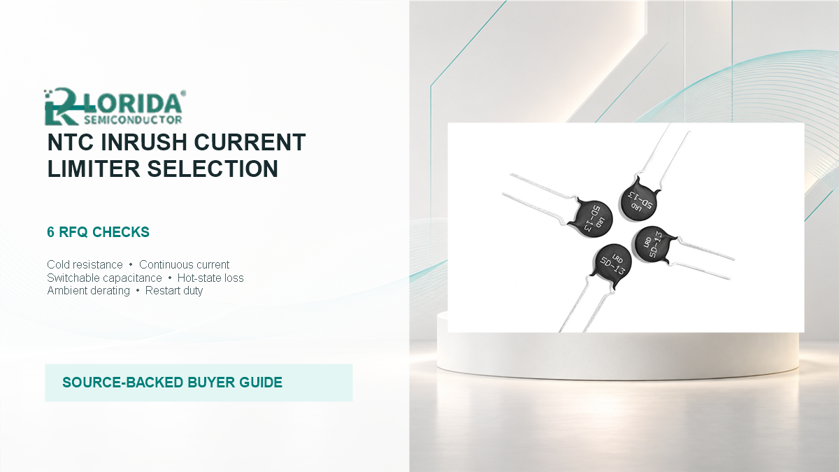
Select an NTC inrush current limiter by matching six independent conditions: cold resistance R25, maximum continuous current, switchable capacitance or energy, hot-state loss, ambient derating, and restart duty.
Why the same ohmic marking can produce different results
Cold resistance solves only the first instant
At power-on, an uncharged bulk capacitor can look close to a short circuit. The NTC is placed in series so its cold resistance limits that first charging current. As current heats the ceramic, resistance falls and the normal operating loss becomes lower.
A preliminary cold-path estimate can use Ohm's law, but it is not a component approval. For example, a 325 V peak source and a desired 25 A first-peak ceiling imply about 13 ohm of total cold-path resistance before accounting for source impedance, rectifier impedance, capacitor ESR, tolerance, and waveform timing.
Energy and normal current create a second thermal problem
The limiter must absorb the energy required to charge the capacitor without exceeding its thermal capability, then carry the normal current without overheating. TDK therefore treats maximum switchable capacitance and maximum continuous current as independent criteria rather than consequences of R25.
The six checks every RFQ should contain
Turn a part request into circuit conditions
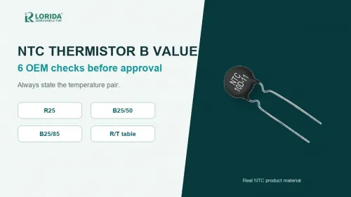
The LORIDA NTC thermal resistor category lists disc families such as 5D-5, 8D-5, 10D-5, 16D-7, 20D-5, and 33D-5. These names are useful for locating candidate families, but the filename or disc diameter should never replace a verified datasheet and application calculation. For temperature-sensing terminology, see the related guide on NTC thermistor B-value checks; B-value is important in sensing work but does not by itself rate an inrush limiter for capacitor charging.
How to compare candidates without mixing unrelated ratings
Read one supplier table across all required columns
The table below uses published TDK examples to show why nominal resistance alone is not a complete comparison. These figures are reference examples from TDK, not LORIDA product specifications.
| TDK example | R25 | Ctest at 230/240 V AC | Maximum continuous current | Approx. disc diameter |
|---|---|---|---|---|
| S153 | 4.7 ohm +/-20% | 100 uF | 3 A | 8.5 mm |
| S237 | 5 ohm +/-20% | 700 uF | 5 A | 15 mm |
| S364 | 4 ohm +/-20% | 1,000 uF | 9.5 A | 21 mm |
| S30 | 4 ohm +/-20% | 3,500 uF | 23 A | 33 mm |
| S36 | 2 ohm +/-20% | 13,050 uF | 35 A | 39 mm |
Two examples can be close in R25 yet very different in current, switchable capacitance, and diameter. The S153 and S364 rows differ by only 0.7 ohm in nominal R25, but the cited current ratings are 3 A and 9.5 A, while the cited test capacitances are 100 uF and 1,000 uF. That is why an RFQ that says only "4-5 ohm NTC" is incomplete.
Apply ambient derating before choosing a smaller disc
Ambient temperature changes allowable current. In TDK's application note, derating for several S153 through S464 families generally begins above 65 deg C, while the S237 curve begins above 25 deg C; the plotted permissible-current factor reaches zero by 170 deg C.
Installation and restart risks that buyers often miss
Do not parallel ordinary NTC inrush limiters
TDK explicitly warns against parallel connection. If one device heats slightly faster, its resistance falls, it takes more current, and the imbalance can accelerate until that branch is overloaded.
Specify the shortest realistic off-time
A warm NTC needs time to cool before its resistance returns toward R25. A brief outage can therefore reconnect the capacitor while the limiter is still hot and low in resistance. The RFQ should state the shortest restart interval, expected brownout behavior, and whether the DC link retains charge.
A practical RFQ worksheet for supplier comparison
Record circuit inputs before asking for a part number
A useful RFQ starts with the equipment, not with a copied thermistor label. Record the minimum and maximum line voltage, frequency, rectifier arrangement, total effective bulk capacitance, capacitor tolerance, precharge state, and expected source impedance.
Mechanical information matters too. Include maximum disc diameter, body thickness, lead pitch, lead length, board clearance, mounting orientation, nearby heat sources, airflow, coating or potting, and the distance to temperature-sensitive parts.
Ask the supplier to return evidence, not only a quotation
The supplier response should identify the exact ordering code and datasheet revision, R25 tolerance, rated continuous current with its ambient condition, switchable capacitance or energy with its stated test voltage, maximum body dimensions, lead spacing, operating-temperature limits, derating curve, and any recommended minimum spacing.
Finally, preserve the selected evidence with the approved drawing and sample result. Incoming inspection can confirm markings and dimensions, while design validation should reproduce the worst cold start, high-line start, low-temperature start, hot restart, maximum-load current, blocked-airflow condition, and expected switching repetition.
Frequently asked questions
How do I choose the R25 value for an NTC inrush limiter?
Choose R25 from the maximum acceptable first current peak, then verify the result with the complete source and charging path. Begin with peak line voltage and the desired current ceiling, but subtract or model source impedance, wiring, rectifier impedance, capacitor ESR, and any precharge resistance already present.
Can two NTC inrush current limiters be connected in parallel?
No - ordinary NTC inrush limiters should not be paralleled to increase current capacity. Their negative temperature coefficient creates a current-hogging mechanism: the branch that warms first drops in resistance, draws more current, and becomes still hotter.
Why can an NTC fail to limit a hot restart?
A hot NTC may fail to limit the second surge because its resistance has not recovered to the cold R25 value. During normal operation the part self-heats and its resistance can fall by roughly a factor of 10 to 50 according to TDK guidance.
Does a larger NTC disc always provide better protection?
No - a larger disc often supports more thermal capacity or current, but it does not automatically provide the required cold resistance, energy rating, hot loss, or restart behavior.
Primary sources
TDK, NTC inrush current limiter application note - selection criteria, current range, connection rules and derating.
TDK, NTC thermistors application notes - operating principle and hot-resistance behavior.
TDK product search - cited S-series example values.
TDK S30/S36 technical article - high-current family ranges.
TDK NTC ICL catalogue overview - family comparison context.
Prepare a complete NTC RFQ
Send the line voltage and frequency, total bulk capacitance, desired first-peak limit, normal RMS or DC current, maximum ambient temperature, shortest restart interval, available disc space, lead spacing, and bypass method. LORIDA can then compare a candidate family against stated application inputs without guessing missing conditions.