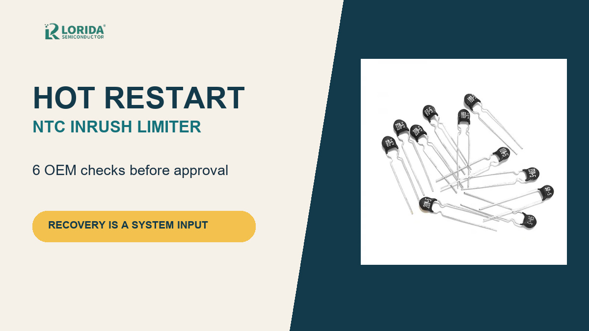
An NTC inrush current limiter may provide much less protection during a hot restart because its resistance remains low until the device cools. OEM teams should define the shortest off-time, residual bus voltage, ambient conditions and acceptable restart current, then verify the complete circuit rather than relying on the cold R25 value alone.
Key Takeaways
What an OEM restart review must prove
Cold resistance is not the resistance available a few seconds after shutdown.
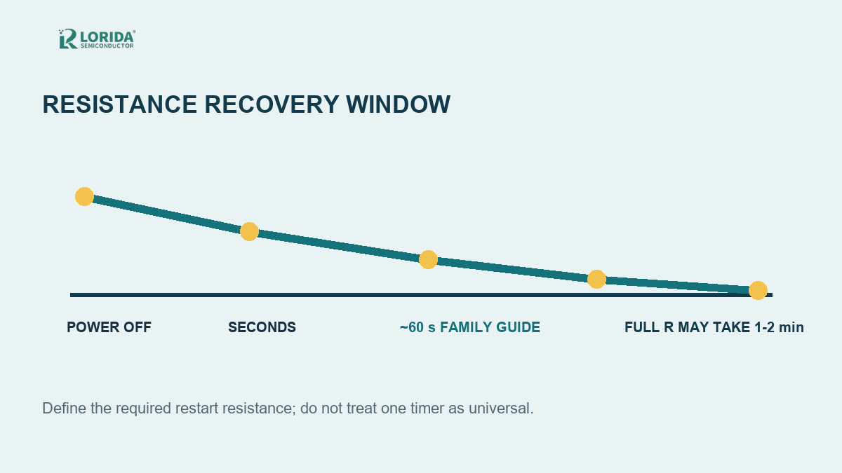
TDK guidance gives a broad 30-second to 2-minute cool-down range and notes that full resistance may require 1-2 minutes, depending on type.
Thermal time constant and full resistance recovery are different checkpoints.
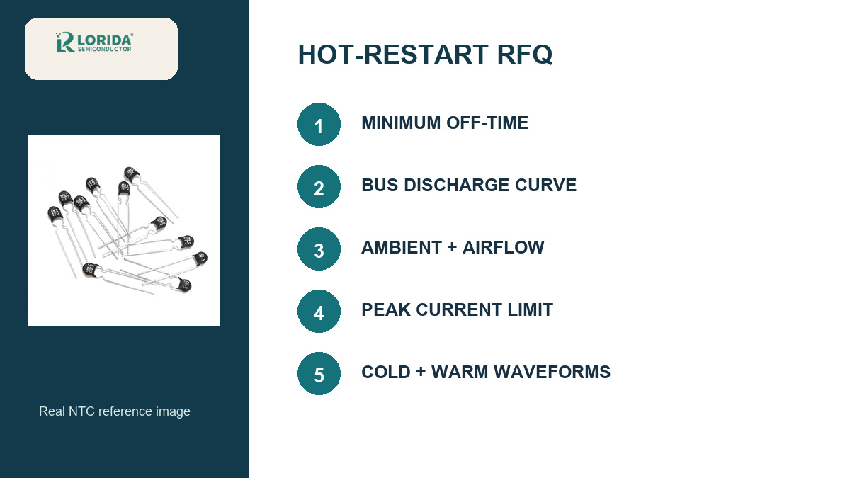
The RFQ must include off-time, bus discharge behavior, ambient, airflow, mounting and restart sequence.
Repeated restarts require circuit-level measurement and may justify a bypass or active inrush approach.
Why Does a Hot NTC Limit Less Inrush Current?
Its useful resistance falls as temperature rises
An NTC limiter starts with relatively high resistance at room temperature. The first charging current heats the disk, and its resistance drops so continuous power loss is reduced. TDK's application note states that hot resistance can fall by a factor greater than 30-50 compared with the cold condition. If power returns before cooling restores sufficient resistance, the next surge can approach the unprotected circuit's current.
This is why a successful cold-start test does not prove warm-restart behavior. The engineer must test realistic interruption durations, initial line phase, filter-capacitor state and worst-case ambient. The device should not be selected from nominal resistance alone.
How Long Does an NTC Need to Recover?
Use a resistance target, not one universal waiting time
TDK gives a typical cool-down range of 30 seconds to 2 minutes depending on disk size, while another current TDK application note says full resistance is reached only after 1-2 minutes depending on the ICL type. Ametherm recommends at least 60 seconds for its Surge-Gard family and also notes that mounting and ambient alter recovery. These are manufacturer references, not a universal timer for every part.
A thermal time constant describes a defined fraction of a temperature transition; it is not automatically the time to recover the full R25 resistance. For example, Vishay's SL121R008 datasheet lists a 40-second thermal time constant, but that number alone does not approve a 40-second restart. Define the minimum resistance needed for the next start and measure when the installed device reaches it.
| Restart input | Why it matters | Evidence to request |
|---|---|---|
| Minimum off-time | Sets available cool-down | Restart sequence and measured resistance |
| Residual DC-bus voltage | Changes recharge energy | Discharge curve and bleeder data |
| Ambient and airflow | Changes starting temperature | Worst-case enclosure test |
| Mounting and spacing | Changes heat rejection | PCB drawing and nearby heat sources |
| Allowed peak current | Protects fuse, bridge and switch | Waveform at cold and warm start |
Six OEM Checks for a Reliable Hot Restart
Convert restart behavior into RFQ data
1. Define the interruption window. State the shortest expected off-time and whether rapid manual cycling, brownouts or automatic retries are possible. 2. Record the energy source. Provide input voltage, frequency, rectifier arrangement and total charging capacitance. 3. Set a current limit. Identify the fuse, bridge, relay, switch or connector that determines the acceptable peak.
4. Describe thermal conditions. Include ambient range, enclosure, airflow, PCB spacing and nearby heat sources. 5. Verify the exact part. Request R25, tolerance, maximum steady-state current, permitted energy, hot resistance and the manufacturer's recovery data. 6. Test the sequence. Capture cold start, minimum-off-time restart and repeated restart waveforms at worst-case line and temperature.
When Should You Consider a Bypass or Active Circuit?
Frequent restarts can change the best architecture
A relay or semiconductor bypass can remove the NTC from the continuous-current path after the initial surge. This reduces steady heating and lets the device start cooling earlier, but it adds timing, control and failure-mode requirements. Active inrush circuits may be more appropriate where immediate hot restart is mandatory. The choice is a system decision, not a universal upgrade.
Vishay's 2025 current-protection guide shows possible NTC locations on the AC input or after the bridge on the DC side. Placement affects voltage stress, current waveform, heat and service behavior. Document the actual topology in the RFQ and do not copy a position from a generic diagram without reviewing safety and equipment standards.
What Exact Data Should the Supplier Return?
Make every offered part traceable
Ask for the manufacturer, series, part number, datasheet revision, R25 and tolerance, maximum current, energy rating, resistance at operating current, body dimensions, lead spacing, thermal time constant and recovery guidance. A current product-specific example, Vishay SL121R008, lists 1 ohm R25 with +/-20% tolerance, 8 A maximum steady-state current to 65 C, 40 J recommended energy and 0.043 ohm at full rated current. Those figures illustrate the required fields; they are not LORIDA-wide values.
Review the NTC thermal resistor category, the earlier general NTC selection guide, and the LORIDA product range before sending a model-specific request.
Frequently Asked Questions
Buyer questions about recovery and restart
Why does my fuse blow only during a quick restart?
A quick restart can occur while the NTC is still hot and at low resistance, so it limits much less current than it did at the first cold start. The remaining DC-bus voltage, line phase, minimum off-time and component temperature all affect the next surge. Measure the restart waveform at the shortest real interruption and worst-case ambient. Also verify the fuse time-current behavior, bridge rating and charging capacitance. Do not solve the symptom by increasing the fuse rating without a coordinated circuit review.
Is 60 seconds always enough for an NTC to reset?
No, 60 seconds is a manufacturer-family guideline, not a universal reset time. TDK describes ranges extending from 30 seconds to 2 minutes and notes that full resistance may take 1-2 minutes depending on the ICL type. Device mass, prior current, mounting, airflow and ambient temperature all change cooling. Define the resistance required for safe restart, then use supplier curves or direct measurements to determine when the installed part reaches that value under the equipment's worst-case conditions. Record the test method and acceptance limit.
Is thermal time constant the same as cool-down time?
No, thermal time constant describes a specified fraction of a thermal transition, while full cool-down or resistance recovery can take longer. A datasheet value such as 40 seconds should not be interpreted automatically as permission to restart after 40 seconds. The application needs a defined resistance target and a measured or manufacturer-supported recovery curve. Confirm the test conditions because free-air data may not match a crowded enclosure, hot PCB or part mounted near a transformer, rectifier or heatsink. Validate the installed assembly at worst-case ambient.
Can a bleeder resistor fix hot-restart inrush?
A bleeder resistor can reduce stored bus voltage, but it does not by itself guarantee that the NTC has cooled enough. It changes the energy remaining in the capacitors and can alter the next charging event, while the thermistor's temperature and resistance follow a separate thermal process. Evaluate both curves: bus discharge versus time and NTC resistance recovery versus time. Include power loss, discharge safety, component tolerances and fault conditions. If immediate restart is mandatory, a bypass or active inrush architecture may deserve a system-level review.
Sources and Review Note
Primary references for the numerical checkpoints
Last Updated: September 21, 2026. Technical review used the cited manufacturer sources. No individual author or reviewer name is displayed because a confirmed public byline identity was not available.
Send Your Hot-Restart Requirements
Get a document-based NTC review
Share input voltage, capacitance, minimum off-time, ambient, peak-current limit and mechanical envelope. Contact LORIDA with your restart sequence.