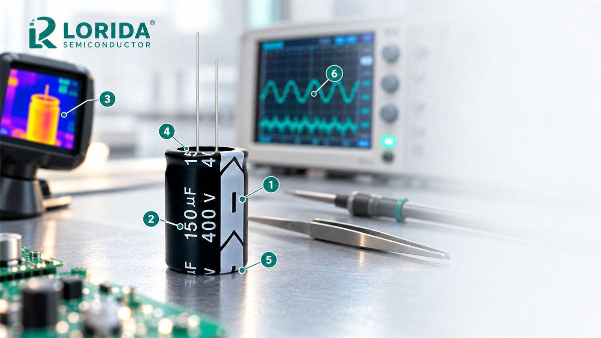
A bulging aluminum electrolytic capacitor must be removed from service and investigated, not pushed back into shape or powered again. Bulging usually means internal pressure has risen or the vent has operated, but the root cause can be reverse polarity, overvoltage, excessive ripple heating, abnormal charge-discharge duty, high ambient temperature, or mechanical damage. The six checks below help an OEM or maintenance team separate the visible symptom from the electrical and thermal evidence before selecting a replacement.
Key Takeaways
What the visible symptom can and cannot prove
Bulging is a reject condition, but it does not by itself identify the root cause.
Polarity and peak applied voltage should be checked before assuming the capacitor was underspecified.
Ripple current must be evaluated by frequency because ESR and allowable ripple are frequency-dependent.
Case temperature alone is incomplete; record ambient temperature, self-heating, airflow, spacing, and nearby heat sources.
Keep the failed part and the undamaged comparison sample separate so photographs and measurements remain traceable.
Replacement approval should use the original series specification or an approved equivalent, not sleeve diameter and capacitance alone.
Why an Electrolytic Capacitor Bulges
Gas generation raises internal pressure
Aluminum electrolytic capacitors use an electrolyte and a polarized oxide dielectric. Nichicon explains that reverse voltage, voltage above the rated value, extreme ripple, or AC voltage can generate gas and operate the pressure-relief vent. Nippon Chemi-Con likewise describes overvoltage and reverse voltage as conditions that increase leakage current, heat, gas generation, and internal pressure. The vent is therefore a protective feature that reduces rupture risk; it is not an indicator that the capacitor may remain in service.
Thermal stress can be electrical or environmental
Ripple heating follows an I²R relationship, so a current increase can raise internal loss faster than a simple current ratio suggests. Chemi-Con notes that rated ripple is commonly specified at 120 Hz or 100 kHz, depending on series, and provides a frequency-corrected RMS method when several ripple components are present. Its technical example gives self-temperature-rise limits of 15°C at 85°C or below and 5°C at 105°C; those are example limits, not universal LORIDA specifications. Always use the approved series data.
Six Diagnostic Checks Before Replacement
Checks 1–2: document the symptom, then verify polarity and voltage
Do not infer polarity only from pad shape. Verify the assembled orientation against the schematic and BOM, then capture the actual terminal waveform. Chemi-Con reports that even about 1 V of reverse voltage can reduce capacitance in its example, while 2–3 V reverse can increase loss and leakage and shorten life. That evidence is a warning threshold from a manufacturer technical note, not permission to operate below 1 V reverse.
Checks 3–4: reconstruct ripple heating and the thermal environment
A current probe reading without frequency content cannot be compared reliably with a single catalog ripple number. Chemi-Con states that short inrush events may be 10 to 1,000 times normal current for milliseconds; a single event may have little thermal energy, while frequent repetition can overheat internal and external connections. For life estimation, the same manufacturer describes an approximate 10°C life-doubling rule between 60°C and 95°C, with important limits outside that range. Use it only for screening, never as a warranty calculation.
Checks 5–6: inspect mechanical conditions and compare electrical evidence
Mechanical findings matter because deformation, blocked vent space, damaged seals, and stressed connections can change the failure path. Electrical comparison also needs controlled conditions: ESR and impedance vary with temperature and frequency, and leakage depends on applied voltage, temperature and time. If a capacitor has bulged, destructive analysis belongs with a qualified laboratory or the supplier; ordinary incoming inspection should not re-energize it.
Symptom-to-Evidence Diagnostic Table
Use the table to plan tests, not to declare a cause
| Observed evidence | Possible mechanism to investigate | Minimum confirming record |
|---|---|---|
| Raised or opened top vent | Internal gas from reverse voltage, overvoltage, excessive ripple, AC stress, or abnormal charge-discharge duty | Polarity audit, terminal voltage waveform, ripple spectrum, thermal log |
| Sleeve shrinkage or nearby PCB discoloration | External heat source, inadequate airflow, soldering heat, or internal self-heating | Case/ambient temperatures, airflow state, neighboring component temperatures |
| Seal residue or electrolyte evidence | Pressure rise, seal deterioration, mechanical stress, or prolonged high temperature | Photographs before cleaning, lot traceability, mounting and environment review |
| High ESR or low capacitance without obvious bulging | Dry-out, thermal ageing, unsuitable test condition, or connection damage | Test frequency, temperature, method, instrument, known-good comparison |
| Repeated failures at one circuit position | Circuit duty or layout issue rather than an isolated component defect | Position history, waveforms across load modes, BOM/series verification, thermal map |
Replacement and RFQ Evidence
Do not approve a substitute by capacitance and voltage alone
Include capacitance, rated voltage, polarity, case dimensions, lead spacing, terminal style, maximum operating temperature, ripple-current table with reference frequency, ESR or impedance condition, endurance requirement, vent orientation, mounting constraints, and the measured application waveforms. If the failed part is used in a rectifier, inverter, charger, power supply, motor drive, or frequent on/off circuit, state the actual duty instead of a generic application name.
For related selection work, review LORIDA's aluminum electrolytic capacitor range, the leakage-current test checklist, the ESR versus impedance RFQ guide, and the vent-clearance PCB checklist.
Frequently Asked Questions
Can a slightly bulging electrolytic capacitor still be used?
No, a visibly bulging aluminum electrolytic capacitor should be removed from service. The shape change indicates abnormal internal pressure or vent operation, and its remaining electrical and safety margin cannot be established by appearance. Do not press the vent flat, puncture the case, or apply voltage to see whether it still works. Isolate and discharge the equipment according to the equipment maker's procedure, photograph the part in place, record polarity and circuit position, and quarantine it for supplier or laboratory analysis. Replace it only after checking the circuit conditions that may have caused the symptom, including reverse voltage, overvoltage, ripple-current spectrum, ambient temperature, airflow and mechanical restraint.
Does bulging always mean the capacitor was defective?
No, bulging alone cannot distinguish a component defect from application stress. Manufacturer guidance identifies reverse voltage, overvoltage, excessive ripple or AC stress, repeated charge-discharge duty, high temperature and mechanical damage as possible contributors to pressure rise or failure. A useful investigation therefore combines lot and supplier traceability with circuit evidence. Capture terminal voltage during startup, steady load and shutdown; measure ripple by frequency; log case and ambient temperature; inspect vent clearance, adhesive and lead stress; and compare a known-good sample using the same test frequency and temperature. Only after these records are reviewed should the team classify the event as isolated, lot-related, assembly-related or application-related.
Which measurements should be included in a failure report?
Include measurements that reproduce the electrical, thermal and mechanical conditions at the failed position. Record the capacitor series, lot, markings, polarity, circuit reference, rated values, operating hours if known, startup and shutdown voltage waveforms, steady DC voltage, reverse excursions, ripple-current RMS and spectrum, case and ambient temperatures, load state, airflow and neighboring heat sources. For bench comparison, state capacitance, ESR or impedance frequency, leakage test voltage, test time, temperature and instrument identity. Add clear photographs before cleaning or removal, plus the schematic, BOM revision and mounting details. These records let a supplier compare the application with the approved specification without guessing from a single photograph.
How should a removed high-voltage capacitor be handled?
Follow the equipment manufacturer's discharge and lockout procedure, then keep the removed part shorted or packaged only as that approved procedure specifies. Aluminum electrolytic capacitors can develop recovery voltage after an initial discharge. Nippon Chemi-Con reports that recovery voltage may peak roughly 10–20 days after terminals are opened and recommends, for its described use case, discharge through about 100–1,000 Ω before use; those figures are manufacturer guidance, not a universal service instruction. Personnel should use appropriately rated tools, verify voltage at the terminals, avoid touching or puncturing the case, and quarantine swollen or leaking parts in accordance with site safety and waste rules.
Primary Sources and Scope
Manufacturer guidance used for this diagnostic workflow
Nichicon, Application Guidelines for Aluminum Electrolytic Capacitors — pressure-vent operation and field failure modes.
Nippon Chemi-Con, Aluminum Electrolytic Capacitor Technical Note — reverse voltage, overvoltage, ripple heating, inrush and life calculations.
Nippon Chemi-Con, Pressure Valves on Aluminum Electrolytic Capacitors — purpose of the pressure vent.
Nippon Chemi-Con, Recovery Voltage — delayed voltage recovery and discharge guidance.
Panasonic Industry, Aluminum Electrolytic Capacitors Technical Guide — construction and application guidance.
Last Updated: October 31, 2026. Numerical examples above describe cited manufacturer guidance and must not be treated as a substitute for the approved specification of a particular LORIDA series.
Send the failure evidence before requesting a replacement
Share clear photos, existing capacitor markings, circuit position, voltage and ripple waveforms, temperature records, dimensions, lead spacing and required quantity. LORIDA can then discuss a technically relevant capacitor option without treating a bulged part as a simple capacitance-and-voltage substitution.