A DC-link discharge resistor must be selected from the capacitor energy, initial and target voltage, required discharge time, pulse repetition, mounting and protection logic—not from resistance and steady-state wattage alone. The resistor sees its highest electrical stress at the start of discharge, while repeated events and restricted cooling determine the thermal result. This guide gives OEM buyers a source-backed RFQ and validation method without treating worked examples as universal product ratings.
Key Takeaways
What to confirm before sampling
Calculate stored energy from capacitance and maximum bus voltage.
Define the safe target voltage and maximum permitted discharge time.
Check peak voltage, initial current, pulse energy and repetition against the exact resistor series.
State the mounting surface, airflow, ambient range and cooldown time.
Validate the complete discharge waveform and fault response in the real assembly.
Why Is a Discharge Resistor a Pulse Component?
The stored energy is set by capacitance and voltage
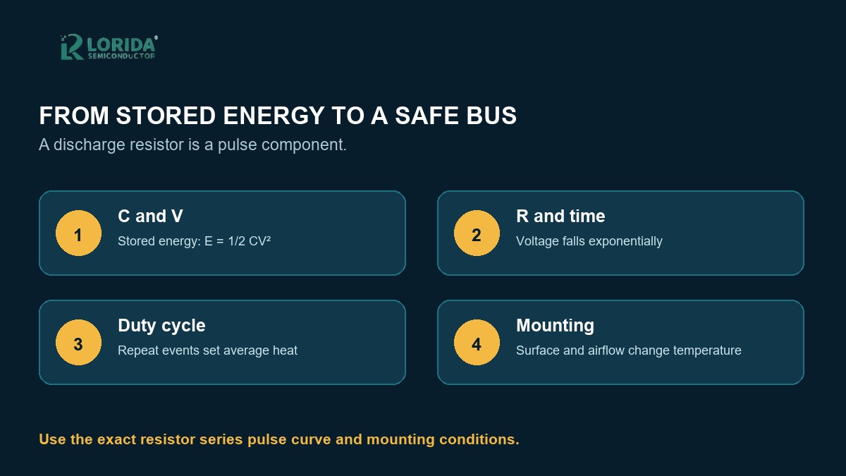
For a charged capacitor, the stored energy is E = 1/2 CV². Voltage is squared, so a voltage increase changes energy much faster than a similar percentage increase in capacitance. Vishay’s pulse-handling guide gives a worked example in which a 2 µF capacitor charged to 400 V stores 0.16 J. That number is an illustration of the equation, not a suggested LORIDA rating. Buyers should calculate the actual worst-case bus condition and identify whether the event is occasional, repetitive or emergency-only.
Voltage and power are highest at the start
A passive RC discharge follows an exponential voltage decay. Texas Instruments expresses it as U(t) = U0 × e−t/RC. The initial current is approximately U0/R and the initial resistor power is U0²/R. This is why a component that appears acceptable by average energy may still fail a working-voltage, overload or pulse-power limit. Compare all four checks: resistor value, voltage across the element, energy per event and the manufacturer’s pulse curve.
How Do You Calculate the Required Resistance?
Start with the target voltage and time
For a passive resistor across a capacitor, rearranging the exponential equation gives R = −t / [C × ln(Vt/V0)]. Use the maximum initial voltage, the minimum effective capacitance where it controls timing, the required safe voltage and the shortest permitted time. Then check tolerances and the discharge path resistance. A schematic assumption is not enough; the final waveform should be measured at the actual bus.
Keep worked examples tied to their source
TI’s 2024 application brief uses an example of 1000 V, 1 mF, a 60 V target and a five-second limit. Its equation produces about 1777.2 Ω. The document then evaluates a 1600 Ω standard value, reporting 60 V in about 4.5 seconds, an initial current of 625 mA and an initial power of 625 W. These six exact values describe TI’s example only. They show why time, current and peak power must be checked together; they are not default requirements for an industrial inverter or a LORIDA resistor.
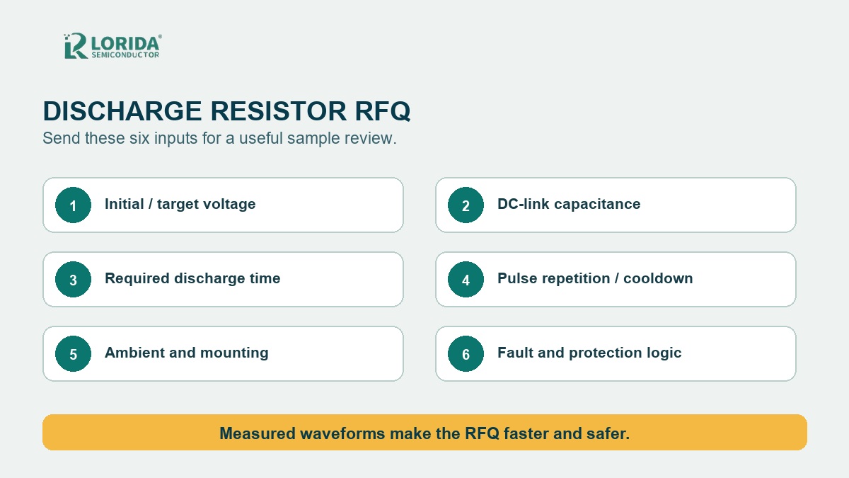
| RFQ input | Why it matters | Validation evidence |
|---|---|---|
| Initial and target voltage | Sets voltage stress and decay ratio | Worst-case bus waveform |
| Capacitance and tolerance | Sets stored energy and time constant | Specified and measured range |
| Discharge time | Defines resistance window | Time to safe threshold |
| Repetition and cooldown | Controls average heating | Temperature over repeated cycles |
| Mounting and ambient | Changes heat transfer | Case and nearby-part temperature |
What Changes the Real Thermal Result?
Repetition converts pulse energy into heat
One emergency discharge with a long cooldown is different from a repeated production cycle. Send the number of events, minimum interval, normal operating duty and worst credible fault sequence. Vishay asks capacitor-discharge users for resistance and tolerance, capacitance, charge voltage, repetition, maximum ambient temperature and any other applied power. Those inputs let the supplier check both a single event and cumulative temperature rise.
Mounting is part of the rating
An aluminum-housed resistor transfers heat through its mounting surface. A flat interface, suitable thermal material, fixing torque, enclosure airflow and clearance from temperature-sensitive parts can change the case temperature materially. Do not assume the printed wattage applies in free air or on an unspecified plate. Ask for the exact series’ mounting conditions, working-voltage limit, overload curve and temperature derating, then reproduce those conditions during sample validation.
How Should OEM Buyers Build the RFQ?
Send circuit and mechanical information together
Provide maximum continuous and transient bus voltage, capacitor nominal value and tolerance, target voltage, maximum discharge time, switching device, expected repetition, ambient range, airflow, mounting plate and space envelope. Include the preferred resistance tolerance, lead or terminal direction, insulation and creepage constraints, and whether the resistor remains connected continuously or is switched only during a discharge event. For replacements, add photos, dimensions and the original circuit function without assuming the visible marking proves interchangeability.
State the safety concept without outsourcing it
TDK’s PFC installation guide explains that discharge resistors protect personnel and support re-switching. For the cited capacitor families, it states 75 V or less within 60 seconds, with some types within 90 seconds, and says capacitors should reach 10% of rated voltage or below before re-switching. Those values apply to the identified TDK products and context. Your equipment’s governing standard, risk assessment, interlocks and verification plan must define the actual safe threshold.
How Should the Sample Be Validated?
Measure the waveform and temperature
Test at the highest repeatable bus voltage and worst cooling condition. Record initial voltage, current, time to target voltage, resistor case temperature and nearby-component temperature. Repeat the worst permitted cycle until temperature stabilizes or the defined test ends. Verify that the switching device and control logic actually connect the resistor in normal shutdown and every intended fault mode. Testing high-voltage assemblies requires qualified personnel, appropriate probes and an approved safe-work procedure.
Review evidence before volume approval
Compare the measured event with the exact resistor datasheet and supplier pulse assessment. Recheck resistance drift, mounting integrity, insulation, terminal temperature and visible damage after the test. Keep the waveform, setup photos and thermal results in the approval record. For related component selection, see LORIDA’s DC-link film capacitor guide, aluminum-housed resistor guide and engineering contact page.
Frequently Asked Questions
Can I select a discharge resistor from watts and ohms alone?
No, watts and ohms alone are not enough. The resistor also has to withstand the initial applied voltage, peak current, energy per event, pulse shape and repetition. Mounting and ambient temperature then determine how quickly heat leaves the component. Send the capacitor value, maximum voltage, target voltage, required time, event frequency and cooling arrangement. The supplier can compare that profile with the exact series’ pulse and overload data, while your team validates the waveform and temperature in the complete equipment.
Why can a resistor pass one discharge but fail in repeated operation?
Repeated operation can accumulate heat faster than the assembly removes it. A single pulse may stay within the energy capability, yet a short interval can raise the resistor case, mounting plate and nearby air before the next event. Higher starting temperature reduces thermal margin. Specify on-time, off-time, events per hour, other continuous power and the worst fault sequence. Validation should repeat the real cycle and monitor temperature, rather than testing only one room-temperature discharge.
Does a lower resistance always make the system safer?
No, a lower resistance shortens discharge time but increases initial current and power. It can also raise stress on the switching device, wiring, terminals and resistor element. A higher resistance reduces initial current but may miss the required safe-voltage time. Use the exponential decay equation to establish a resistance window, then check tolerance, working voltage, pulse energy and switching limits. Confirm the result with a measured waveform at the maximum expected bus voltage.
What information should I send for a replacement resistor?
Send the circuit duty and mechanical evidence, not only the old marking. Include maximum bus voltage, DC-link capacitance, target voltage and time, repetition, ambient, mounting surface, dimensions, terminals, photographs and the original part reference. Explain whether the component is a permanent bleeder, a switched discharge resistor or part of a pre-charge network. Similar-looking aluminum housings can contain different elements and pulse capabilities, so sample verification remains necessary before volume replacement.
Need a Discharge Resistor Sample Review?
Send the six RFQ inputs
Share your bus voltage, capacitance, target voltage, discharge time, repetition and mounting conditions. LORIDA can review the application inputs and prepare a resistor sample proposal for your system-level validation.
Send Your RequirementsLast Updated: September 22, 2026. Technical references: Texas Instruments SLAAEL5 (2024); Vishay Dale Wirewound Resistors Pulse Handling Capabilities; TDK Electronics PFC capacitor installation and maintenance instructions. Always use the specification for the exact component supplied.