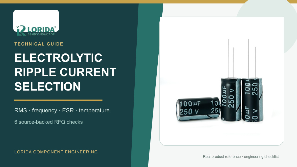
Select an aluminum electrolytic capacitor for ripple current by converting the real waveform to a frequency-corrected RMS value, then checking ESR heating, ambient temperature, mounting and required life against the exact series data. Rated capacitance and voltage alone do not show whether a capacitor can tolerate the combined 100/120 Hz rectifier component and switching-frequency current inside a PFC stage, inverter or industrial power supply. This guide gives buyers six source-backed checks for an RFQ and validation plan.
Key Takeaways
What the RFQ must contain
Send current at each significant frequency, not only one peak-current number.
Compare frequency-corrected RMS current with the exact series rating and its stated reference frequency.
Measure case temperature in the real enclosure and account for the difference between case and element core.
Validate temperature rise, capacitance, leakage and ESR or dissipation factor after the intended duty.
Why ripple current shortens capacitor life
Internal loss becomes heat
Nichicon expresses capacitor loss as W = IAC² × Re + VDC × IDC. When DC leakage is small, the practical term becomes approximately W = IAC² × Re. Nippon Chemi-Con gives the same relationship and shows temperature rise as ΔT = IR²R/(βA), where R is internal resistance, A is can surface area and β is the radiation constant. Because current is squared, a modest current increase can create a much larger heat increase. That heat accelerates electrolyte loss, raises ESR and reduces expected life.
Frequency changes ESR and allowable current
ESR is frequency-dependent, so the same RMS amperes at 120 Hz and 100 kHz do not necessarily create the same loss. Nichicon's application note gives example frequency coefficients for 315–450 V capacitors of 0.77 at 50 Hz, 1.00 at 120 Hz, 1.30 at 1 kHz and 1.43 at 50 kHz or above. These are example coefficients, not universal LORIDA values. The exact offered series data sheet must govern the calculation.
Six ripple-current RFQ checks
1. Break the waveform into frequency components
Provide an oscilloscope export or FFT showing the rectified mains component, switching-frequency component and any sidebands. Chemi-Con specifically illustrates a waveform containing 120 Hz, 80 kHz and 100 kHz components and warns that the low-frequency component can contribute more internal heating. Record operating modes, load range, startup, regenerative events and fault clearing separately rather than averaging them into one untraceable number.
2. Convert to the reference-frequency RMS value
Use the exact data-sheet multipliers to convert each current component to the series reference frequency. Chemi-Con combines components as Ifo = √[(If1/Ff1)² + (If2/Ff2)² + …]. This root-sum-square method prevents a high-frequency current from being treated as if it caused the same ESR loss as a low-frequency component. Do not add peak currents directly or apply a multiplier borrowed from another voltage, case size or capacitor family.
3. Check voltage and current together
Confirm that the DC voltage plus ripple peak stays below the rated voltage and that polarity never reverses. Nichicon's current application guidance explicitly requires both operating temperature and applied ripple current to remain within specification. A voltage margin does not compensate for excessive ripple heating. State maximum bus voltage, minimum bus voltage, ripple peak-to-peak value, RMS current, waveform crest factor and abnormal transients.
4. Measure the thermal condition at the capacitor
Give the temperature beside the capacitor, measured case temperature, airflow, enclosure position and nearby heat sources. Nichicon's example core-temperature-rise limits for over-315 V snap-in capacitors decrease from 30°C at 40°C ambient to 15°C at 85°C and 5°C at 105°C. Those values are illustrative; every product family can use different limits. Rubycon also notes that the core is hotter than the surface when ripple current flows.
5. Match the exact construction
Request the full series, rated ripple current, reference frequency, frequency multipliers, ESR or impedance curve, endurance condition, case size, terminal pattern and mounting restrictions. A radial, snap-in and screw-terminal capacitor can have different heat paths and current capability even when capacitance and voltage match. If capacitors are paralleled, include current-sharing evidence, busbar resistance, terminal torque and cooling symmetry.
6. Define a measurable validation plan
Specify sample count, waveform, ambient temperature, operating duration and stop criteria. Measure stabilized case temperature, current spectrum, capacitance, leakage current and ESR or dissipation factor before and after the run. Chemi-Con recommends thermocouple measurement because ESR depends on temperature and heat radiation depends on installation. A calculated life is an estimate, not a guarantee, so keep margin against the equipment life requirement.
Buyer comparison table
Separate circuit evidence from supplier evidence
| Check | Buyer input | Supplier evidence |
|---|---|---|
| Current spectrum | RMS current by frequency and mode | Reference frequency and multipliers |
| Thermal condition | Ambient, case temperature and airflow | Core-rise limit and endurance basis |
| Electrical margin | DC voltage, ripple peak and polarity | Rated voltage and allowable ripple |
| Release test | Duty profile and equipment life | Capacitance, leakage, ESR and visual limits |
How to prepare the inquiry
Send data before asking for a substitute
Attach the circuit diagram, current waveform or FFT, bus-voltage range, switching frequency, load profile, ambient range, measured case temperature, case and terminal envelope, mounting orientation and required life. Review the LORIDA capacitor product center, compare transient limits with the surge-voltage guide, and use the rapid charge-discharge checklist if the bus cycles deeply. For a model review, send LORIDA the waveform and mechanical envelope.
Frequently asked questions
Can I compare ripple-current ratings from two data sheets directly?
Only after you normalize the reference frequency, temperature, case size and endurance conditions. One series may publish current at 120 Hz while another uses 100 kHz, and their frequency multipliers can differ. The same rated current can also produce different temperature rise because ESR, case surface area and mounting differ. Compare the complete series conditions, then convert the actual current spectrum with each candidate's own coefficients. Validate the selected part in the real enclosure rather than choosing the largest catalog ampere value.
Why is 120 Hz ripple often more damaging than switching ripple?
Aluminum electrolytic capacitor ESR is generally higher at low frequency, so each ampere can create more loss. A mixed waveform must therefore be weighted by the exact series frequency multipliers. Chemi-Con's FFT guidance shows that a low-frequency rectifier component can have a greater heating effect than higher-frequency components in the same waveform. This does not mean switching ripple is harmless. It means the current components must be converted and combined correctly before comparing them with the rating.
What should be measured during a ripple-current sample test?
Measure current spectrum, stabilized capacitor temperature and electrical change under the intended duty. Capture RMS current at each important frequency, bus voltage, ambient temperature, case temperature and airflow. Before and after the test, measure capacitance, leakage current and ESR or dissipation factor at controlled temperature. Inspect the seal, sleeve, vent and terminals. Record sample quantity, instrumentation bandwidth, thermocouple position, duration and stop criteria so the supplier and buyer can reproduce the result.
Primary sources
Manufacturer guidance used for the calculations
Nippon Chemi-Con: Lifetime of Aluminum Electrolytic Capacitors.
Nippon Chemi-Con: Measuring Ripple Current Using FFT Analysis.
Nichicon: Application Guidelines for Aluminum Electrolytic Capacitors.
Send the current spectrum, voltage, measured temperature, mechanical envelope and lifetime target for a source-backed model review.
Last Updated: November 16, 2026. Numerical examples belong to the cited manufacturer guidance and are not blanket LORIDA product specifications. Verify the exact order code and final equipment requirements before approval.