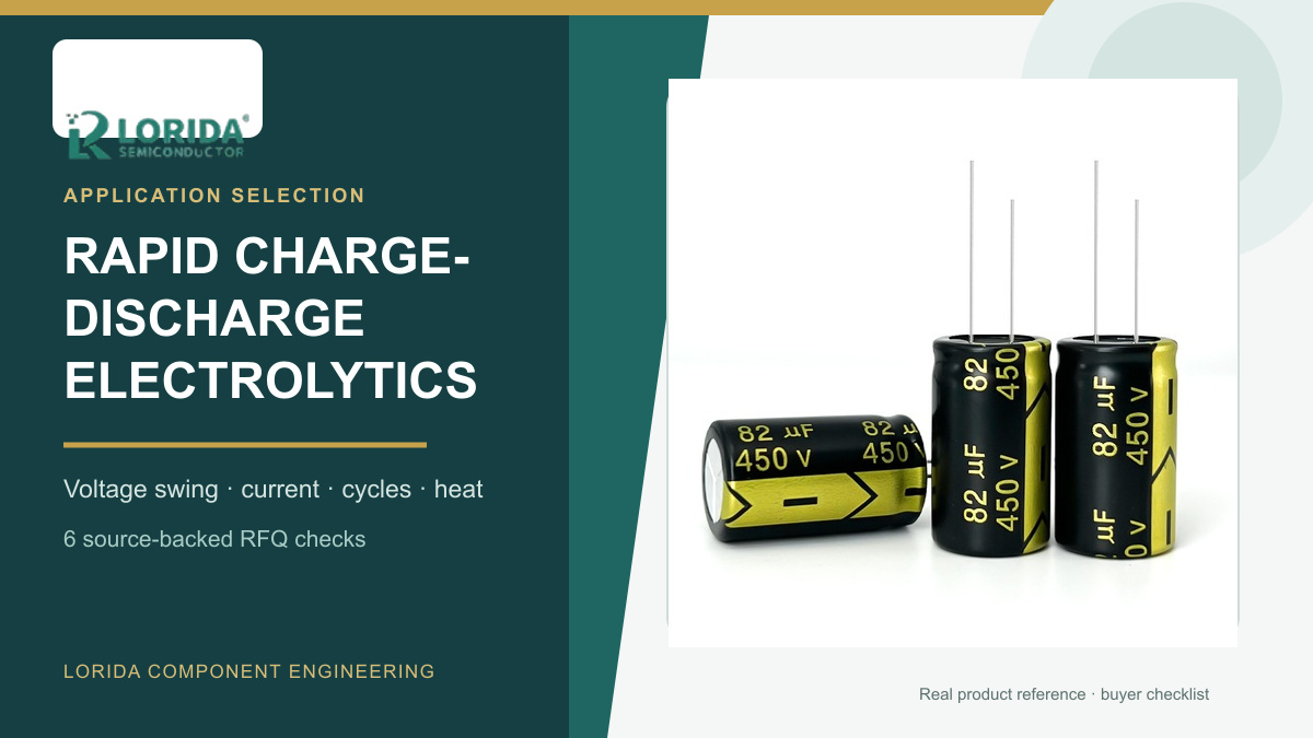
Rapid charge-discharge duty requires an aluminum electrolytic capacitor qualified for the actual voltage swing, current, cycle time, cycle count, temperature and discharge resistance. A general-purpose part may lose capacitance, heat internally, generate gas or operate its pressure vent even when its steady DC voltage appears acceptable. This source-backed guide shows buyers how to turn a servo-drive, inverter or pulsed-power waveform into a complete RFQ and validation plan.
Key Takeaways
What the buyer must define
Do not approve a general-purpose electrolytic capacitor only from capacitance and rated voltage.
Send the maximum and minimum bus voltage, current waveform, charge and discharge time, cycle count, discharge resistance and actual hot-spot temperature.
Treat published test curves as series-specific examples, not universal LORIDA limits.
Validate capacitance, leakage current, dissipation factor or ESR, temperature rise and vent condition after the real duty sequence.
Why repeated cycling changes the capacitor
Charge movement affects the cathode foil
Nichicon explains that discharge moves charge from the anode system toward the cathode foil. Repetition can form additional oxide on the cathode, reduce cathode capacitance and therefore reduce the capacitor's total series capacitance. Its technical note expresses the cathode voltage as Vc = V/(1 + Cc/Ca), linking the stress to the anode-to-cathode capacitance relationship. The practical result is that two capacitors with the same label can behave differently if only one was designed for frequent charge-discharge duty.
Heat and gas create a second failure path
Nippon Chemi-Con and Rubycon both identify internal heating and gas generation as consequences of severe repeated cycling. These effects can raise internal pressure, reduce capacitance, operate the pressure relief vent or cause destructive failure. Chemi-Con also notes that a single start-up inrush may last only milliseconds yet reach roughly 10 to 1,000 times the normal current; repetition changes the thermal decision because connections and the internal element may not cool between events.
Six RFQ checks for rapid charge-discharge duty
1. Capture the complete voltage swing
Record maximum, minimum and steady bus voltage instead of sending only the rated voltage. Include overshoot, regenerative peaks, dwell at each level and any polarity reversal. Chemi-Con's charge-discharge FAQ describes dedicated servo-motor series with a maximum voltage fluctuation of 150 V under its cited conditions. That is a supplier-specific ceiling, not a general limit. The offered series must state its own permitted voltage swing and peak-voltage rule.
2. Quantify current and resistance
Provide peak and RMS current in both directions, charge-path resistance, discharge resistance, switching-device impedance and wiring resistance. Current without duration is incomplete, and resistance without tolerance or temperature is incomplete. Nichicon's published comparison used a 63 V, 10,000 µF example with 2 Ω charge resistance and 100 Ω discharge resistance. Those numbers demonstrate a test configuration; they are not replacement values for another circuit.
3. State cycle time and total count
Define charge time, discharge time, rest time, frequency, daily operating hours and lifetime event count. In Nichicon's example, one cycle was one second of charge plus one second of discharge at 70 °C. The standard capacitor fell about 25% by 1,000 cycles and about 32% by 2,000 cycles, where the plotted example marks vent operation, while the charge-discharge type remained close to its initial capacitance through the longer test.
4. Use actual capacitor temperature
Measure can or core-related temperature under the real enclosure, airflow and neighboring heat sources. Chemi-Con's technical note compares 56 WV, 10,000 µF, 35 × 60 mm samples with 30-second charge and 30-second discharge, a 0.01-second time constant and a 60 °C ambient. Its general-purpose example degrades much more than the special design. The point is not to copy 60 °C, but to test at the equipment's credible hot condition.
5. Match construction and series evidence
Request the exact series data sheet, charge-discharge qualification, case size, terminal style and change-control status. Nichicon's NC series data sheet, for example, cites 50 million cycles at a voltage difference equal to 0.3 times rated voltage and 3 Hz. That result belongs to that series and test basis. It cannot justify a different radial, snap-in, screw-terminal, polymer or hybrid capacitor. Confirm whether the proposed LORIDA part is a directly tested construction or requires a project-specific sample plan.
6. Define post-test acceptance
Set pre-test and post-test limits for capacitance change, leakage current, dissipation factor or ESR, temperature rise, case deformation, seal condition and vent operation. Add photographic inspection and controlled discharge before handling. The acceptance plan should name sample quantity, instrumentation bandwidth, measurement temperature, waveform capture points and stop criteria. Do not declare success merely because the capacitor did not visibly bulge during a short bench run.
Comparison table for a corrective RFQ
Separate equipment inputs from supplier evidence
| Decision input | Buyer evidence | Supplier evidence |
|---|---|---|
| Voltage swing | Vmax, Vmin, overshoot, dwell | Permitted ΔV and peak-voltage basis |
| Current path | Peak/RMS current and resistance | Thermal and connection limits |
| Cycle profile | Times, frequency, lifetime count | Series-specific qualification curve |
| Release criteria | Equipment risk and sampling plan | Capacitance, leakage, ESR/tanδ and visual limits |
How buyers should prepare the inquiry
Send waveform data before requesting a substitute
Attach an oscilloscope export and circuit diagram showing the capacitor bank, precharge path, braking or regenerative path, switching devices and discharge resistor. State capacitance, operating and rated voltage, package, terminal arrangement, mounting, ambient range, airflow, expected life and fault history. Review the LORIDA capacitor product center, compare peak-voltage controls with the electrolytic capacitor surge-voltage guide, and use the DC-link precharge resistor checklist when the startup path is part of the duty. For a model review, send LORIDA the waveform and mechanical envelope.
Frequently asked questions
Can a general-purpose electrolytic capacitor handle repeated discharge?
Not unless the exact series documentation and validation show that it can handle the defined waveform. A part may tolerate an isolated startup event yet degrade under a large voltage swing repeated thousands or millions of times. The result depends on current, charge and discharge resistance, time, temperature, case and internal construction. Send the complete cycle profile and request series-specific qualification evidence. If the application is a servo drive, inverter, welding supply or regenerative bus, reproduce the real sequence in a guarded sample test and measure electrical change rather than relying on a visual inspection alone.
Is inrush current the same as rapid charge-discharge duty?
No, a single short inrush event and a repeated bidirectional or large-swing cycle are different qualification problems. Chemi-Con notes that startup inrush can be many times normal current but may create little heat when it is isolated and very brief. Repetition can prevent cooling and stress terminals, internal connections and foils. Rapid discharge also moves charge to the cathode system and can create electrochemical change. An RFQ should therefore separate startup events, normal ripple, regenerative peaks and deliberate discharge cycles, with time, current and resistance stated for each.
What data should accompany a rapid-cycle capacitor RFQ?
Send the waveform, circuit resistance, thermal conditions, lifetime cycle count and required post-test limits. Include maximum and minimum voltage, peak and RMS current, charge time, discharge time, rest time, repetition frequency, daily hours, discharge resistor, switching topology, ambient range, measured can temperature, capacitance, case and terminal envelope. Add the existing part number, failure photographs and electrical data. Ask the supplier to identify the exact series, applicable qualification, permitted voltage swing, test temperature, sample count and acceptance criteria rather than replying with only a capacitance-and-voltage match.
Primary sources
Manufacturer guidance used for the exact examples
Nippon Chemi-Con: applications involving repeated rapid charging and discharging.
Nippon Chemi-Con technical note: charge-discharge operation and lifetime.
Nichicon: Application Guidelines for Aluminum Electrolytic Capacitors.
Send the voltage and current waveforms, charge/discharge resistance, measured temperature, cycle count and mechanical envelope for a source-backed model review.
Last Updated: November 16, 2026. All numerical examples belong to the cited manufacturer documents and series. They are not blanket LORIDA product specifications. Verify the exact order code and final equipment requirements before approval.