

Aluminum electrolytic capacitor pressure-relief vents need clear space and a safe discharge path so they can operate without being blocked by an enclosure, wiring or the PCB. Official Nichicon and Nippon Chemi-Con guidance specifies at least 2 mm above 6.3-16 mm cases, 3 mm above 18-35 mm cases and 5 mm above cases 40 mm or larger. These are manufacturer guidelines; the exact offered series and equipment safety review remain controlling.
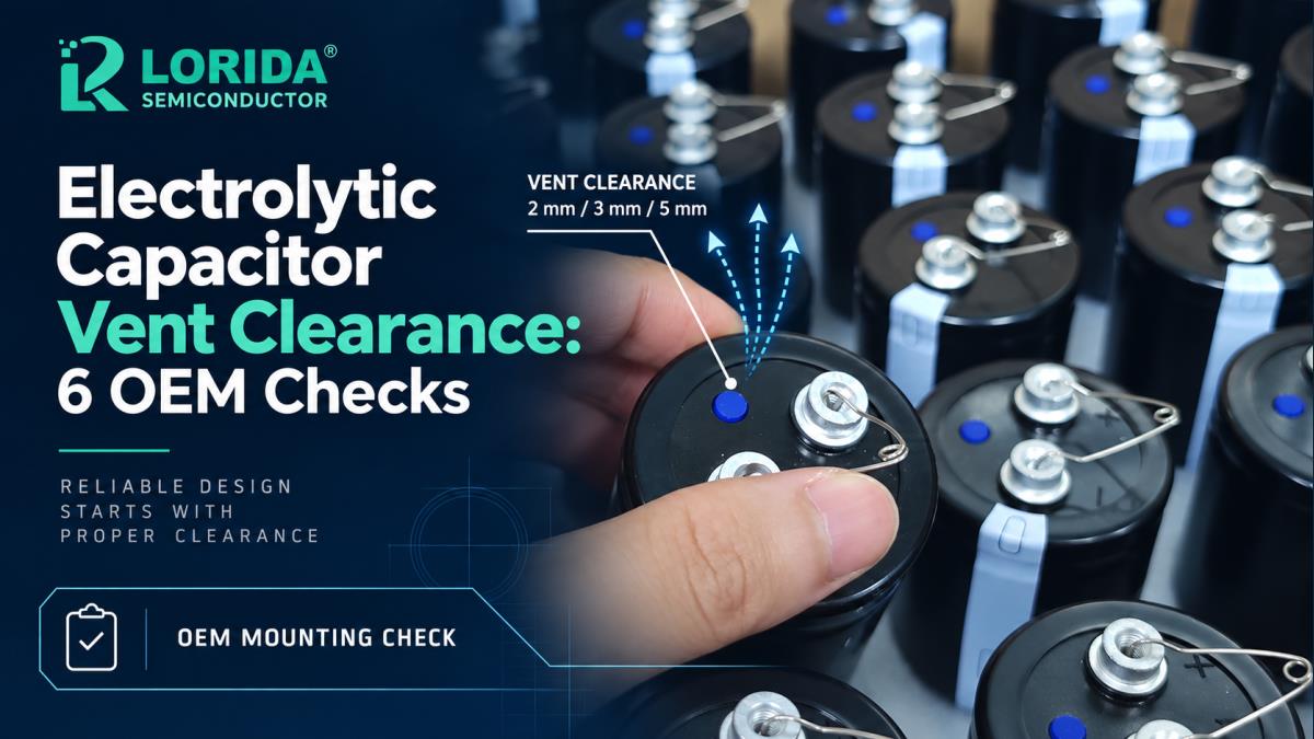
Identify the actual pressure-relief vent and keep its full escape path unobstructed.
Use the applicable series document; do not treat one clearance table as a universal mechanical drawing.
For screw-terminal cans, avoid terminals-down mounting unless the manufacturer explicitly permits it.
Check wiring, PCB copper, ventilation holes, heat sources, clamps and service access together.
Photograph and measure the production first article, not only the CAD model.
Why Does Vent Clearance Matter?
The vent is a controlled pressure-release feature
Non-solid aluminum electrolytic capacitors contain electrolyte and can generate gas if they are electrically or thermally overstressed. Nippon Chemi-Con explains that the pressure vent is intended to reduce the risk of a dangerous rupture when internal pressure rises. The stored energy and possible consequences increase with capacitor size, which is why the vent is especially important on large snap-in and screw-terminal constructions.
What Clearance Values Do Official Guides Publish?
Three case-diameter bands are commonly specified
Nichicon and Nippon Chemi-Con publish the same three minimum clearances unless another product specification applies: 2 mm for case diameters from 6.3 mm through 16 mm, 3 mm for 18 mm through 35 mm, and 5 mm for 40 mm and above. The Chemi-Con product FAQ also notes example vent coverage: surface-mount parts at 10 mm and above, radial-lead parts at 8 mm and above plus some 6.3 mm parts, and all snap-in and screw-terminal sizes. Sources: Nichicon Application Guidelines; Nippon Chemi-Con Precautions; Nippon Chemi-Con Vent FAQ.
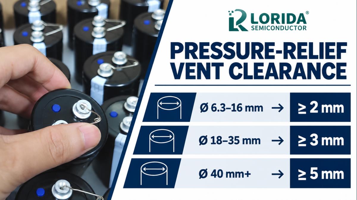
| Case diameter | Published minimum clearance | OEM drawing check |
|---|---|---|
| 6.3-16 mm | 2 mm above the vent | Verify the exact part has a vent and that no label, shield or enclosure blocks it. |
| 18-35 mm | 3 mm above the vent | Check component height tolerance, PCB warp and neighboring hardware. |
| 40 mm and above | 5 mm above the vent | Review the full gas path, terminal guards, busbars, clamp and cabinet lid. |
| Vent facing the PCB | Series-specific | Provide a matching ventilation hole when manufacturer guidance requires it. |
How Should Screw-Terminal Capacitors Be Oriented?
Do not assume every physical orientation is safe
TDK states that screw-terminal capacitors with a vent in the cover disk must not be mounted with terminals facing down unless otherwise specified. For horizontal mounting, TDK recommends placing the pressure-relief vent at the 12 o'clock position and says upright mounting is preferred. Nichicon similarly requires screw-terminal capacitors to be installed with the end-seal side facing up and, for horizontal installation, the positive terminal upright.
What Must Be Checked Around the PCB and Enclosure?
Keep copper, holes and heat sources away
Nippon Chemi-Con says not to locate a wire or circuit pattern over the vent. If a vent faces the PCB, its guidance calls for a ventilation hole beneath it. The same document says copper traces should be 1 mm, preferably 2 mm or more, away from the capacitor body near the seal side. It also warns against placing heat-generating parts nearby or on the opposite side of the PCB directly under the capacitor.
Check mechanical tolerance, not nominal CAD only
Stack capacitor height, PCB warp, bracket tolerance, lid deflection and assembly variation. Confirm the final harness, cable ties and terminal covers do not reduce the vent gap below the documented minimum.
Which Six Checks Belong in the OEM Review?
Use one checklist from RFQ through first article
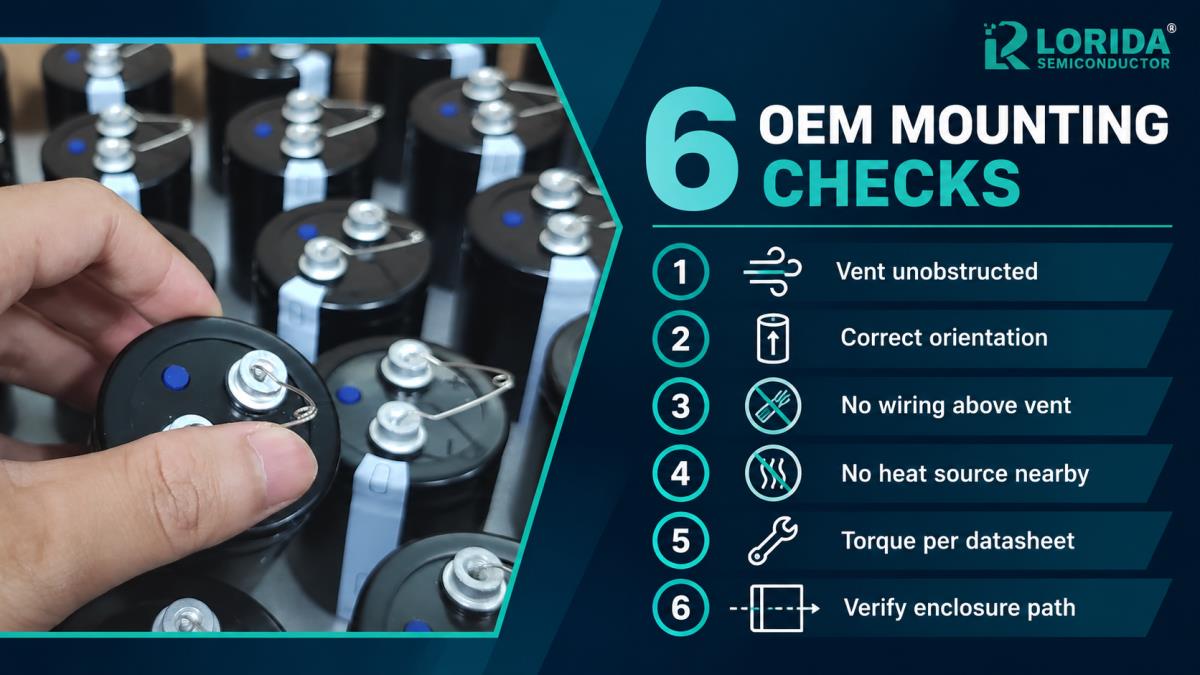
First, identify vent location and construction from the exact series drawing. Second, apply the documented clearance and include tolerance. Third, confirm the allowed upright or horizontal orientation. Fourth, remove wiring, PCB copper and enclosure features from the escape path. Fifth, apply only the terminal and clamp torque in the selected series documentation. Sixth, validate the assembled first article with photos and physical measurements. This prevents a mechanical rule from being lost between component selection, cabinet design and factory assembly.
How Should Buyers Write the RFQ?
Request the evidence needed for mechanical approval
Provide the target capacitance, rated voltage, ripple spectrum, ambient and case temperature, expected life, case diameter and height, terminal style, polarity control, mounting position, clamp or stud arrangement, enclosure gap and nearby heat sources. Ask the supplier for the current data sheet, controlled drawing, vent location, allowed orientations, clearance rule, terminal torque, clamp torque, mass and dimensional tolerances. Include any vibration, shock, altitude or unusual atmosphere requirements.
Connect the mechanical review to electrical duty
Vent clearance does not correct electrical overstress. The sum of DC voltage and ripple peak must remain within the selected capacitor's approved limit, and ripple current must stay within the applicable frequency and temperature conditions. Buyers can review the LORIDA capacitor product center, a representative screw-terminal product page, the ripple-current selection guide, and the storage acceptance guide.
Frequently Asked Questions
Is 2 mm enough above every electrolytic capacitor vent?
No, 2 mm is not enough for every aluminum electrolytic capacitor. Nichicon and Nippon Chemi-Con publish 2 mm for 6.3-16 mm cases, 3 mm for 18-35 mm cases and 5 mm for 40 mm and larger cases unless another specification applies. The equipment drawing must use the exact case diameter and series documentation, then include mechanical tolerance and the complete escape path. A nominal 2 mm CAD gap can disappear after PCB warp, lid deflection, bracket variation or harness installation. Confirm the production first article with a physical measurement and photograph.
Can a screw-terminal capacitor be mounted terminals down?
Generally no, not unless the selected manufacturer's specification explicitly permits that orientation. TDK states that screw-terminal capacitors with a cover-disk vent must not be mounted with terminals facing down unless otherwise specified. Nichicon requires the end-seal side facing up. For horizontal mounting, the manufacturer may define the vent or positive-terminal position. Record the approved orientation on the controlled drawing and assembly instruction. Do not infer permission from mechanical fit, a competitor's construction or a photo of another series.
Should the PCB have a hole beneath a downward-facing vent?
Yes when the applicable manufacturer guidance calls for a ventilation hole aligned to a vent facing the PCB. The hole must match the actual vent location and remain unobstructed after soldering, coating, labels and enclosure assembly. However, adding a hole does not automatically authorize a mounting orientation that the selected product forbids. First confirm the series-specific orientation, then design the board and enclosure together. Also review creepage, clearance, contamination, copper keep-outs and the direction in which released material could travel.
Does vent clearance prove the capacitor is correctly selected?
No, vent clearance is only one mechanical safety check. Correct selection also requires rated voltage, ripple voltage, ripple current, frequency correction, temperature, expected life, surge and transient conditions, charge-discharge duty, dimensions, terminals, torque, vibration and system protection. A well-spaced capacitor can still be overstressed electrically, while a correctly rated capacitor can still be installed unsafely. Use the exact series data and validate a first article under the real electrical and thermal profile. Record both mechanical measurements and operating waveforms in the approval package.
Last Updated: September 28, 2026
Prepare a Vent-Clearance RFQ
Send the capacitor drawing and enclosure section
Share the case size, terminal style, mounting orientation, vent path, electrical duty and first-article plan. LORIDA can review candidate aluminum electrolytic capacitor constructions for sample validation.
Send Your Capacitor Requirements


