MOV varistor leakage current should be diagnosed at the exact datasheet voltage, temperature, and stabilization time before the part is judged acceptable or damaged. A reading without those conditions cannot be compared with a limit because an MOV is intentionally nonlinear and its low-current behavior changes strongly with voltage and temperature. This guide gives procurement, quality, and engineering teams six repeatable checks for separating a test-setup problem from real varistor degradation.
Use the specified maximum continuous operating voltage, not the nominal varistor voltage.
Record temperature, polarity or waveform, dwell time, and fixture background with every result.
Compare only against the exact series datasheet or an approved incoming-inspection limit.
A rising trend after surge exposure is more informative than one isolated reading.
What does MOV leakage current mean?
The high-resistance region is below the clamping region
At normal circuit voltage, a metal-oxide varistor operates in its high-resistance region and only a small current flows. During an overvoltage event, the device moves into a highly conductive region and clamps the transient. TDK describes the left-hand portion of the voltage-current curve below 1 mA as the high-resistance mode used to evaluate worst-case leakage. The 1 mA point is commonly used as the reference for varistor voltage, but it is not the same as the continuous operating voltage.
One manufacturer example shows why voltage must be exact
TDK's technical example for an S14K14 device gives a 22 V varistor voltage at 1 mA with a ±10% tolerance. The same example specifies 18 VDC as the maximum continuous operating voltage. Depending on the device's position within the tolerance band, leakage at 18 VDC can range from 6 µA to 200 µA, while operation at 10 VDC lowers the stated maximum to 2 µA. These figures illustrate the diagnostic principle; they are not universal LORIDA limits and must not be applied to a different MOV code.
Six checks for an unexpectedly high reading
1. Confirm the exact device code and approved limit
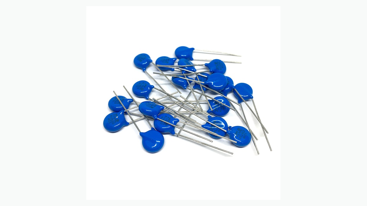
Read the disk marking and match it to the approved drawing, supplier datasheet, or purchase specification. Disk diameter, nominal varistor voltage, tolerance code, and series construction can change the limit. Do not infer a pass/fail value from color or physical size. For an incoming lot, record the full marking and lot identity before testing so that a mixed reel or substituted series is not mistaken for electrical drift.
2. Apply the correct continuous voltage
Use the datasheet's maximum continuous AC RMS or DC voltage for the selected method. Do not apply the 1 mA varistor-voltage value as a continuous test voltage. TDK's example also notes that 14 VAC has a 19.8 V peak value, calculated with the square-root-of-two relationship. That peak can produce a very different instantaneous current from a lower DC test. State whether the source is DC, AC RMS, or a swept voltage and keep the waveform consistent across comparison samples.
3. Control temperature and stabilization time
Leakage current is temperature sensitive, so compare readings only at the specified ambient or component temperature. Keep the MOV away from recent soldering heat, surge pulses, and warm fixtures until it reaches the test condition. Apply voltage for the defined dwell time before recording the result, and use the same timing for the reference sample and suspect sample. If the current continues rising instead of stabilizing, stop the test safely and investigate self-heating or damage.
4. Measure fixture and instrument background
Open-circuit the fixture at the intended voltage and record its background current. Contaminated insulation, humid surfaces, flux residue, damaged leads, and insufficient meter resolution can create a false high result. Use guarded connections where appropriate, keep exposed conductors separated, and verify the source voltage with a calibrated instrument. Subtracting or ignoring background without a documented method can hide a real problem, so retain both raw and corrected values.
5. Review surge, thermal, and storage history
A MOV that has absorbed repeated transients can shift electrically before obvious cracking or discoloration appears. Compare the suspect part with an unexposed control from the same approved series. Record the surge waveform, peak current, pulse count, interval, and ambient temperature when available. Littelfuse describes MOV operation across leakage, normal varistor, and high-current regions; the high-current upturn can occur from roughly 50 A to 50,000 A depending on device size. That broad range reinforces why stress history must be matched to the exact part.
6. Use a trend and an approved acceptance rule
Do not reject a shipment from one unexplained value. Test an agreed sample size, include a known-good reference, and compare the distribution with the approved limit. A consistent shift across the lot suggests a series, process, or test-condition difference; isolated outliers suggest handling damage, contamination, or mixed material. If the purchase specification has no leakage-current criterion, pause disposition and obtain the series datasheet or an engineering-approved limit rather than inventing one after results are known.
| Symptom | First check | Evidence to retain |
|---|---|---|
| Whole lot reads high | Voltage, temperature, series identity | Marking photos, source setting, ambient record |
| Only a few outliers | Contamination, damage, mixed parts | Individual traceability and visual inspection |
| Current rises during dwell | Self-heating and prior surge stress | Current-time curve and component temperature |
| Reading changes by fixture | Background leakage and insulation | Open-fixture value and instrument ID |
What should an RFQ or inspection plan specify?
Define conditions before requesting a number
For a useful quotation or incoming-inspection plan, provide the MOV code or electrical target, maximum continuous AC and DC voltage, expected surge waveform, peak current, pulse count, ambient range, mounting method, and required safety or qualification evidence. Also state the leakage-current test voltage, temperature, dwell time, sample size, and acceptance rule. LORIDA's MOV varistor product category can be used to identify candidate disk formats, while the final electrical limit must come from the confirmed series specification. Buyers can also review the earlier MOV selection checklist and MOV aging checks.
Frequently asked questions
What leakage current is acceptable for an MOV?
The acceptable leakage current is the maximum stated for the exact MOV series under its specified voltage and temperature. There is no universal microamp value for all disk sizes and voltage codes. TDK's S14K14 example spans 6 µA to 200 µA at 18 VDC because the tolerance band affects current, but that example cannot be transferred to another part. Record the full marking, test voltage, ambient temperature, dwell time, instrument range, and approved datasheet limit. If the series document does not define a limit, obtain an engineering-approved criterion before accepting or rejecting the lot.
Can I test leakage at the nominal varistor voltage?
No, the nominal varistor voltage is normally a reference measured at a defined current, often 1 mA, rather than the continuous operating point. Applying it as a steady test voltage can force the MOV into a much more conductive region and produce a misleading result or heating. Use the datasheet's stated DC or AC continuous operating voltage and its leakage-current method. If you run a voltage-current sweep for characterization, use current limiting, document the ramp rate, and stop at the approved endpoint. Never mix sweep data with a steady-state leakage acceptance limit.
Does high leakage prove the MOV has been damaged by a surge?
High leakage can indicate degradation, but it does not prove surge damage until test conditions and setup errors are excluded. Excess voltage, elevated temperature, insufficient stabilization, surface contamination, fixture leakage, wrong series identity, or mixed parts can all raise the measured current. Retest with a known-good reference under identical controlled conditions and inspect the current-time behavior. Then review surge pulse count, waveform, peak current, spacing, and component temperature. A repeatable shift from the reference after documented stress is stronger evidence than one isolated measurement.
What information should I send with an MOV leakage-current RFQ?
Send the circuit voltage, MOV marking or target rating, surge duty, temperature range, and the exact leakage-current test condition. Include AC RMS and DC maximum voltage, expected transient waveform, peak current, pulse count, interval, mounting space, lead spacing, coating requirement, operating ambient, and any required compliance evidence. For inspection, add test voltage, temperature, dwell time, meter range, fixture background, sample size, and acceptance limit. Photographs of the existing component and its marking help prevent a disk-size or voltage-code mismatch. Use the LORIDA contact page to submit those inputs for candidate review.
Sources
Primary technical references
TDK Electronics, SIOV metal oxide varistors: General technical information.
Littelfuse, Varistors: Basic Properties, Terminology and Theory.
Send the device marking, circuit voltage, surge duty, ambient range, and leakage-current test method so the candidate and acceptance evidence can be compared on the same basis.
Request a technical quotationLast Updated: November 4, 2026