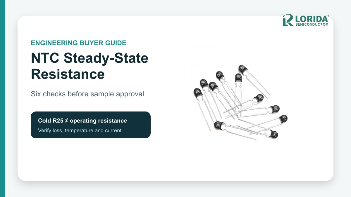
An NTC inrush current limiter must be checked at its real steady-state current and temperature, because its operating resistance can be far below its cold R25 value. OEM buyers should request the exact part's R25, maximum current, Rmin or resistance-versus-current data, thermal limits and installed waveform before approving a sample.
Key Takeaways
What the buyer must prove
R25 describes the cold part at 25 °C; it does not directly state the hot loss during normal operation.
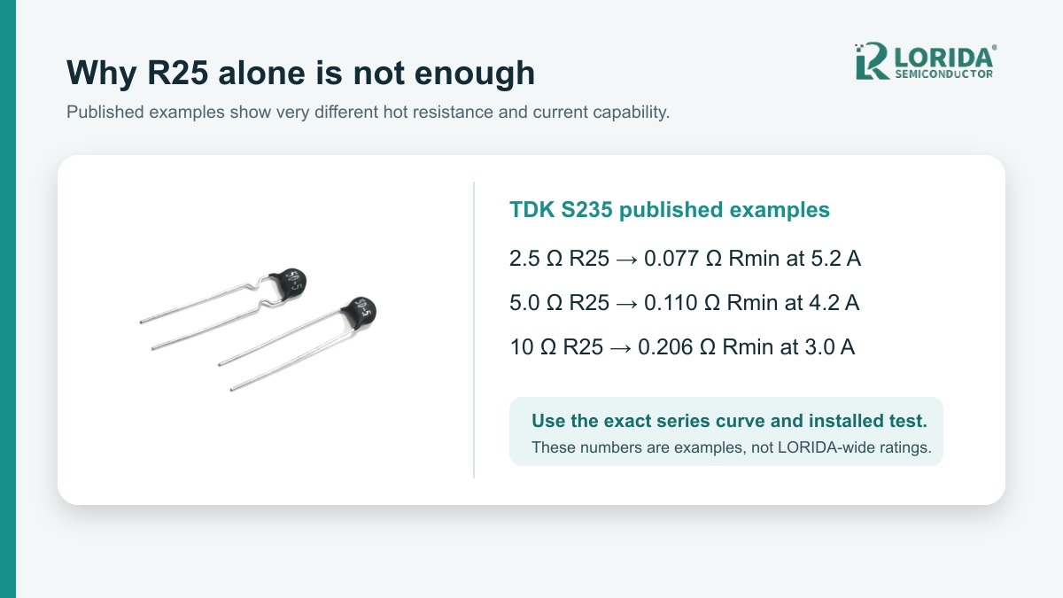
TDK's S235 examples publish both R25 and Rmin at rated current, showing why the two values must not be interchanged.
Maximum current, ambient temperature, airflow, lead spacing and nearby heat sources belong in the same review.
Use manufacturer curves for screening and an installed waveform and temperature test for final approval.
Record the exact series, part number and datasheet revision so every numerical claim remains traceable.
Why Does Steady-State Resistance Matter?
The limiter changes after start-up
An NTC device begins relatively cold and resistive. The charging pulse heats it, its resistance falls, and the lower hot resistance reduces continuous voltage drop. That behavior is useful, but it creates two separate design questions: can the cold part limit the initial surge, and can the hot part carry normal current without excessive loss or temperature? A selection based on only one question is incomplete.
Continuous loss is related to current squared multiplied by operating resistance. The correct resistance must come from the exact part's published data or a controlled measurement at the intended current and thermal condition. Do not insert R25 into a steady-state loss estimate unless the part truly remains near 25 °C, which is not the normal inrush-limiter operating state.
What Do Published Datasheets Show?
Three TDK examples make the distinction visible
TDK's S235 family datasheet lists a 2.5 Ω R25 option with 5.2 A maximum current and 0.077 Ω Rmin at maximum current. The same table lists a 5 Ω option with 4.2 A maximum current and 0.110 Ω Rmin, and a 10 Ω option with 3 A maximum current and 0.206 Ω Rmin. These are series-specific published examples, not universal values and not LORIDA product ratings.
The figures also show why a higher cold resistance does not automatically mean a better design. Cold resistance affects the first surge, while maximum current and hot resistance shape continuous heating and voltage drop. The permitted test capacitance, energy, ambient range and required recovery behavior must still be checked in the same datasheet.
| Published TDK S235 example | R25 | Maximum current | Rmin at Imax, 25 °C | Buyer use |
|---|---|---|---|---|
| B57235S0259M0** | 2.5 Ω | 5.2 A | 0.077 Ω | Compare cold surge and hot loss |
| B57235S0509M0** | 5 Ω | 4.2 A | 0.110 Ω | Check current and thermal margin |
| B57235S0100M0** | 10 Ω | 3 A | 0.206 Ω | Verify voltage drop at load |
Six OEM Checks Before Sample Approval
Turn the electrical duty into traceable RFQ inputs
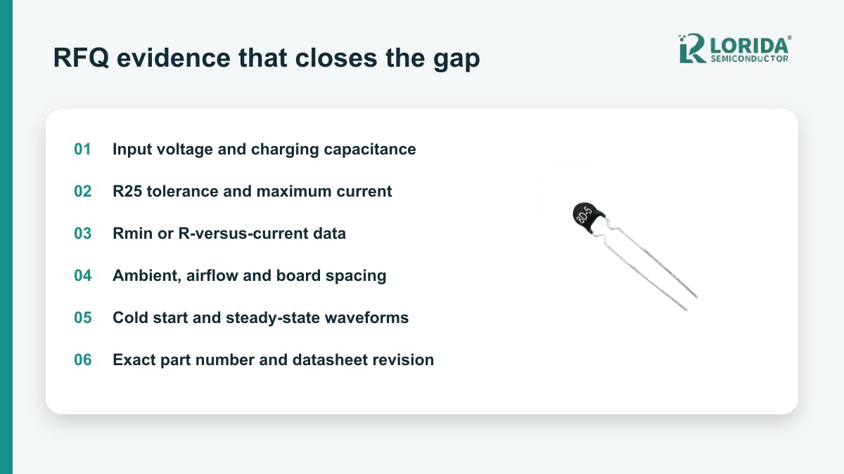
Define the source and charging load. State minimum and maximum input voltage, frequency, rectifier arrangement, total charging capacitance, residual voltage and any PFC or bypass timing.
Request R25 and tolerance. TDK's S236 family data gives ±20% resistance tolerance as the standard family figure and notes tighter tolerance options may be available. Use the exact ordering code.
Request maximum current and hot-resistance data. Ask for Rmin or the resistance-versus-current curve at the intended ambient. Do not assume that two parts with the same R25 have the same current capability.
Check energy and repetition. A single cold-start pass does not approve frequent starts. Provide starts per hour, minimum off-time and abnormal retry sequences.
Describe the thermal installation. TDK's S236 family lists about 10 mW/K dissipation factor and about 70 s thermal cooling time constant in air. Those values are mounting-dependent family examples; the installed assembly needs its own temperature validation.
Capture evidence. Record cold-start current, steady RMS current, voltage drop, part temperature and warm-restart waveform at worst-case line and ambient.
How Should Buyers Estimate Continuous Loss?
Use the operating point, then verify it
For a first screening calculation, multiply the square of the expected RMS current by the resistance at that operating point. For example, a published 0.110 Ω Rmin at 4.2 A corresponds to about 1.94 W by I²R, but that arithmetic is only an illustration. Rmin is defined under the manufacturer's stated condition, and real resistance and temperature depend on airflow, lead length, PCB copper, enclosure temperature and neighboring heat sources.
Compare the estimate with the exact part's power and temperature limits, then measure the assembled equipment. A thermocouple placement that changes airflow or touches a lead instead of the body can mislead the review. Record stabilization time, ambient, input voltage and load so the test can be repeated by the supplier and the OEM.
What Should the Supplier Return?
A part-number-specific evidence pack
Require manufacturer, series, complete ordering code, datasheet revision, R25 and tolerance, maximum steady current, permitted charge energy or test capacitance, Rmin or resistance-current curve, maximum body temperature, dimensions, lead spacing, coating and approvals. Ask the supplier to identify which figures are guaranteed limits, typical values or application examples.
For related purchasing context, review the LORIDA NTC thermal resistor category, the general NTC selection guide, and the hot-restart guide. Send the original part number, circuit duty and installation evidence for a model-specific comparison.
Frequently Asked Questions
Can I calculate normal voltage drop from R25?
No; R25 normally overstates the resistance of a hot NTC carrying its intended current. Use the exact part's R-versus-current data, Rmin definition or measured operating resistance under the specified ambient and mounting condition. R25 is still essential for the first cold charging event, but it answers a different question. When the datasheet does not provide the needed operating point, request manufacturer confirmation and measure voltage and current after thermal stabilization in the finished assembly. Record the method because airflow, lead length, PCB copper and nearby components can change the result.
Does the same R25 mean two NTC parts are interchangeable?
No; identical cold resistance does not prove equal current, energy, hot resistance or mechanical fit. Compare complete ordering codes and current datasheets. Check maximum current, Rmin or resistance curve, energy or test capacitance, tolerance, diameter, lead spacing, coating, approvals and temperature limits. The TDK examples above show that R25 is only one column in the selection table. A replacement also needs cold-start, steady-state and warm-restart tests in the real equipment before release. Record the original and candidate waveforms side by side, including peak current, pulse duration, steady voltage drop and stabilized body temperature.
Why is the NTC hotter in our enclosure than on the bench?
Restricted airflow and nearby heat sources can raise the operating temperature even when electrical current is unchanged. Free-air curves do not automatically represent a closed power supply, dense PCB or hot cabinet. Document enclosure temperature, orientation, copper area, lead length, spacing and adjacent rectifiers, transformers or heatsinks. Measure after the system reaches thermal equilibrium at maximum line and load. If the body temperature or voltage drop exceeds the approved margin, revisit the part, spacing, bypass strategy or inrush architecture. Repeat the measurement on production-representative boards and include sensor position, stabilization time and instrument uncertainty in the test report.
What evidence should accompany a sample request?
Provide the complete start-up waveform and thermal duty, not only a resistance and disk size. Include input range, frequency, rectifier topology, total capacitance, peak target, normal RMS current, starts per hour, minimum off-time, ambient range, airflow, board spacing and size limits. Ask the supplier to return the exact part number, current datasheet and a table mapping every requirement to a published rating or a clearly marked test result. This makes the sample review auditable and prevents typical values from being mistaken for guaranteed limits.
Sources and Review Note
Primary references for numerical examples
Last Updated: October 15, 2026. Technical review used the cited manufacturer sources. No individual author or reviewer name is displayed because a confirmed public byline identity was not available.