Store aluminum electrolytic capacitors in a controlled environment, preserve lot traceability, and assess the need for voltage treatment before applying full rated voltage after long storage. A practical release decision should use the capacitor maker’s storage limit, actual temperature and humidity history, package condition, solderability, initial leakage behavior, and the application’s ability to tolerate inrush. The six checks below turn a shelf date into documented evidence instead of a simple pass/fail guess.
Key Takeaways
What a release decision should establish
Use the product series specification first; a general storage guideline cannot replace it.
Record temperature, relative humidity, sunlight, corrosive-gas exposure, packaging, and storage duration.
Separate electrical readiness from solderability: a part can pass one concern and still fail the other.
Do not apply full voltage blindly when long storage may have raised initial leakage current.
Define the series resistor, voltage, duration, monitoring, discharge, and acceptance test before reforming.
Keep the lot, date code, inspection result, and treatment record linked to the released inventory.
Why Storage Changes the Release Risk
The oxide layer can recover, but the first power-up still matters
An aluminum electrolytic capacitor’s dielectric is an aluminum oxide layer. TDK explains that voltage-free storage can deteriorate that layer, especially at higher temperatures, because it is not continuously regenerated. When voltage is later applied, leakage current can be much higher than normal while the oxide reforms. TDK states that the initial leakage may reach up to 100 times the normal level during the first few minutes after prolonged storage. The current normally declines as the dielectric regenerates, but the application must be able to tolerate that transient safely.
Heat, humidity, and time affect different properties
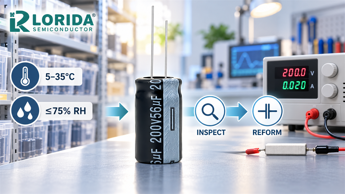
High storage temperature accelerates chemical change and leakage-current growth. High humidity can oxidize leads or terminals and reduce solderability even when the capacitor still appears normal. Nichicon recommends storage from 5°C to 35°C at 75% relative humidity or less. Nippon Chemi-Con gives the same recommended temperature and humidity range and says typical storage limits depend on product but are commonly 2 to 3 years. These values are useful screening references; the approved series data and documented warehouse history remain controlling.
Six Storage and Reforming Checks
Checks 1–2: identify the inventory and reconstruct the environment
Do not substitute the purchase date for manufacturing age when a date code is available. TDK recommends storing general aluminum electrolytic capacitors at 5–35°C and no more than 75% RH, and notes that parts should be mounted within one year of delivery to help prevent PCB solderability problems. That recommendation addresses assembly readiness; it is not a blanket electrical expiration date.
Checks 3–4: inspect packaging, terminals, and the receiving sample
Acceptance data must state how it was obtained. TDK’s general technical information cites leakage-current measurement at 20°C after rated voltage has been applied for 5 minutes for IEC-based acceptance testing, while allowing specified tests from 15°C to 35°C with correction factors. A reading taken immediately after voltage application or at an unreported temperature is not comparable evidence.
Checks 5–6: select a safe power-up path and document release
Manufacturer procedures differ. Nichicon describes approximately 1 kΩ in series, rated voltage, and about 30 minutes for an individual capacitor. Nippon Chemi-Con describes around 1 kΩ and 30 to 60 minutes. TDK’s general storage procedure distinguishes approximately 100 Ω for rated voltage at or below 100 V DC and 1,000 Ω above 100 V DC, applied for one hour. These are not interchangeable recipes. Use only the method issued for the exact approved component or an authorized engineering instruction.
Storage Release Decision Table
Route the lot by evidence, not appearance alone
| Observed condition | Decision question | Required evidence before release |
|---|---|---|
| Within series storage period; controlled 5–35°C and ≤75% RH | Does the application allow direct use under the maker’s rule? | Lot identity, environment log, package inspection, receiving test |
| Unknown or incomplete warehouse history | Can the team prove that storage limits were not exceeded? | Quarantine record, sample plan, electrical and solderability checks, engineering disposition |
| Stored longer than the published limit | Is reforming required and is an approved procedure available? | Series-specific treatment method, guarded fixture, current trend, post-treatment acceptance |
| High temperature or humidity excursion | Could leakage, capacitance, ESR, seals, terminals, or solderability be affected? | Logger data, visual evidence, controlled sample tests, supplier review |
| Already mounted in spare equipment | Can the circuit tolerate high initial leakage and gradual voltage application? | Equipment-maker procedure, monitored power-up plan, voltage/current/temperature record |
RFQ and Warehouse Data to Preserve
Make the next release decision faster
For incoming lots and long-term spares, retain the manufacturer and series, capacitance, rated voltage, case size, terminal style, date code, quantity, delivery date, storage start date, maximum and minimum temperature, humidity history, packaging state, and planned equipment lifetime. Add the application’s startup circuit, precharge path, expected leakage tolerance, and whether parts will be mounted or stored as loose inventory.
For related technical checks, review LORIDA’s aluminum electrolytic capacitor range, the leakage-current test checklist, the bulging-capacitor diagnostic guide, and the ESR versus impedance RFQ guide.
Frequently Asked Questions
Can aluminum electrolytic capacitors be used after two years in storage?
They may be usable, but the decision must follow the exact series specification and the documented storage history. Nichicon states that capacitors stored for less than two years at 5–35°C can generally be used without voltage treatment, while Nippon Chemi-Con says common product storage limits are typically two to three years. Those statements are manufacturer guidance, not a universal expiry rule. Confirm the maker, series, date code, temperature and humidity records, packaging, terminals, solderability, and receiving-test results. If the published period was exceeded or conditions are unknown, quarantine the lot and obtain an engineering or supplier-approved reforming and acceptance plan before release.
Why can leakage current rise during voltage-free storage?
Leakage can rise because the aluminum oxide dielectric is not being regenerated while the capacitor remains unpowered. TDK explains that the effect increases with storage temperature and duration, and initial leakage after long storage may be up to 100 times normal during the first few minutes of power application. The current usually declines as the oxide layer reforms, but excessive initial current can heat the capacitor or overload the application’s startup circuit. Record current versus time, applied voltage, temperature, series resistance, and discharge conditions. Do not judge the lot from a single immediate reading or apply rated voltage without the manufacturer-approved current-limiting method.
Is one reforming procedure suitable for every electrolytic capacitor?
No, reforming procedures vary by manufacturer, voltage class, series, construction, and whether the capacitor is loose or already mounted. Nichicon describes about 1 kΩ and roughly 30 minutes, Nippon Chemi-Con describes around 1 kΩ for 30–60 minutes, and TDK distinguishes approximately 100 Ω at or below 100 V DC from 1,000 Ω above 100 V DC for one hour. These examples show why a generic bench routine is unsafe. Use the approved product document or supplier instruction, define current limiting and monitoring, guard the energized fixture, verify discharge, and record the post-treatment acceptance result.
Does good capacitance prove that a stored capacitor is ready for production?
No, capacitance alone does not prove electrical, mechanical, or assembly readiness. A stored capacitor may have acceptable capacitance while showing increased leakage, higher loss, oxidized terminals, reduced solderability, seal damage, contamination, or incomplete traceability. A production release should combine lot identity and storage records with visual inspection, dimensions, capacitance, dissipation factor or ESR, leakage under a defined method, and solderability evidence when applicable. It should also confirm that the application can tolerate startup current and that any required reforming has been performed under an approved procedure. Keep the results linked to the released quantity and the final engineering disposition.
Primary Sources and Scope
Manufacturer guidance used for this release workflow
Nichicon, Application Guidelines for Aluminum Electrolytic Capacitors — recommended storage environment.
Nichicon, Aluminum Electrolytic Capacitor Technical Notes — storage performance and example voltage treatment.
Nippon Chemi-Con, Storage Conditions and Shelf Life — recommended temperature, humidity, and typical storage limits.
Nippon Chemi-Con, Aluminum Electrolytic Capacitor Storage — leakage mechanism and voltage-treatment example.
TDK Electronics, Aluminum Electrolytic Capacitors — General Technical Information — shelf life, storage, leakage behavior, reforming, and acceptance testing.
Last Updated: November 1, 2026. Numerical examples are attributed to their manufacturers and must not be treated as specifications for an unidentified or different LORIDA series.
Send the storage history before requesting a release decision
Share capacitor markings, maker and series, date code, quantity, warehouse temperature and humidity records, packaging condition, application startup circuit, required lifetime, and any receiving-test data. LORIDA can then discuss a technically relevant component or evidence plan without treating shelf age as the only criterion.